1 Introduction
About this document
Thank you for purchasing Cerevo FlexTally Pro.
This document is a manual explaining how to use the FlexTally Pro, a versatile tally light system (hereinafter referred to as “this product”).Please read this manual to the end before use and use this product with full understanding of how to handle it properly.
What this document covers
This manual is applied to the following Cerevo products.
Product Number |
Product Description |
|---|---|
CDP-FT02A-BP |
Wireless Tally System (JP) |
CDP-FT02B-BP |
Wireless Tally System (US/EU) |
CDP-FT02N-BP |
Wired Tally System |
CDP-FT02A-LP |
Wireless Lamp Unit (JP) |
CDP-FT02B-LP |
Wireless Lamp Unit (US/EU) |
CDP-FT02N-LP |
Wired Lamp Unit |
CDP-FT02A |
Base Unit |
The group of products to which this manual applies is hereinafter referred to collectively as “this product”.
Scope of coverage
This manual describes the general information required to use this product, including installation, setup, operating procedures, and restrictions. In addition to this manual, the following documents are provided.
A quick setup guide included with this product.
Firmware release notes
Revision information
このマニュアルは第1.2.0版(2026年06月30日公開)です。このマニュアルは FlexTally Pro の以下のレビジョンに適用します。
Hardware Revision Rev. A
Revision history
Firmware 1.0 (Released 24th December 2024)
First edition
Firmware 1.0.1 (Released 8th January 2025)
Added equivalent circuit diagram for dry contacts signal input
Firmware 1.0.2 (Released 20th February 2025)
The history has been updated with the release of firmware version v1.0.2.
Firmware 1.1.0 (Released 17th April 2025)
The history has been updated with the release of firmware version v1.1.0.
Firmware 1.1.1 (Released 30th July 2025)
The history has been updated with the release of firmware version v1.1.1.
Firmware 1.1.2 (Released 2nd September 2025)
The history has been updated with the release of firmware version v1.1.2.
Firmware 1.1.3 (Released 15th October 2025)
The history has been updated with the release of firmware version v1.1.3.
第1.1.4版(2026年01月05日公開)
The history has been updated with the release of firmware version v1.1.4.
第1.1.5版(2026年03月23日公開)
ファームウェアバージョン v1.1.5の公開に伴い、履歴を追記した。
第1.1.6版(2026年05月20日公開)
ファームウェアバージョン v1.1.6の公開に伴い、履歴を追記した。
第1.1.7版(2026年06月01日公開)
ファームウェアバージョン v1.1.7の公開に伴い、履歴を追記した。
第1.2.0版(2026年06月30日公開)
ファームウェアバージョン v1.2.0の公開に伴い、履歴を追記した。
Prerequisite knowledge
This manual assumes that the reader has the following knowledge:
Basic understanding of the intended use and operation of tally lamps
Understanding how to install, configure, and operate the video switcher that will be connected to this product
Basic understanding of local networks using Ethernet (IEEE 802.3)
Basic understanding of IP network operation and interface settings
For your safely
Meaning of notation
In this chapter, text beginning with Warning or Caution describes very important information for using this product safely. Warning and Caution indicate the following items, respectively.
Warning
This indicates that failure to follow this instruction may result in death or serious personal injury.
Caution
This indicates that failure to follow this instruction may result in personal injury or damage to the equipment.
Safety warnings and precautions
In the event of an abnormal situation
Warning
If abnormal conditions such as smoke or unusual smells come out of this product or cables, etc., stop using it immediately and disconnect the power supply cable. Continued use under such conditions may result in malfunction, electric shock, or fire. After confirming that no smoke is emitted, contact your dealer or our support center. Do not attempt to repair this product by yourself as it is dangerous.
About power supply
Warning
Use power, power-supply cables and power banks that meet all the requirements described in this manual. Using the incompatible items may result in malfunction of this product, electric shock, overheating, smoking, or fire.
Warning
Never use the power-supply cable if it is damaged, conductor wires are exposed, or is broken. Doing so may result in a malfunction of this product, electric shock, overheating, smoking, or fire.
Warning
Do not use this product with dust or other foreign matter or liquid adhering to the power-supply connector. Doing so may result in a malfunction of this product, electric shock, overheating, smoking, or fire.
Temperature rise
Caution
The surface of this product may become hot due to heat dissipation and may cause burns if touched. Please handle this product with care during and after use until the temperature cools down.
Prohibited acts
Warning
Do not disassemble or modify this product. Doing so may result in malfunction of this product, electric shock, overheating, smoking, or fire.
Warning
Do not short-circuit the connectors of this product or connect devices other than those indicated in this manual. Doing so may result in malfunction of this product, electric shock, overheating, smoking, or fire.
Warning
When connecting external devices to this product, turn off the power of all devices first. Connecting external devices with the power on may cause malfunction or damage to this product.
Installation environment
Caution
Do not use this product under the following conditions or environment. Doing so may result in malfunction, failure, or deformation.
Places directly exposed to wind from heaters, air conditioners, etc., or where there is a sudden change in temperature
Places exposed to direct sunlight or in a car under a hot sun
Places subjected to sea breezes or continuous high humidity
In a liquid or in a corrosive atmosphere
Places subject to strong vibrations
Places where there are strong electromagnetic field
Places where static electricity is generated
Other similar conditions
Approval Information
CDP-FT02A-LP
The Lamp unit, CDP-FT02A-LP, of this product is a specific radio equipment (radio equipment, specific low power device, specified under Article 2, Paragraph 1, Item 8 of the Certification Regulations) that has been certified for its construction design in accordance with the Radio Law of Japan, and can be operated in Japan without a radio station license. The certification number for CDP-FT02A-LP is 001-A21554. This radio equipment cannot be used outside of Japan.
CDP-FT02B-LP
The Lamp Unit, CDP-FT02B-LP, of this product is a product for North America and Europe and cannot be used in Japan.
Frequency band used
CDP-FT02A-LP uses radio waves in the 315MHz band. CDP-FT02B-LP uses radio waves in the 433MHz band.
Precautions for operating wireless equipment
About interference
If you use this product simultaneously with other wireless equipment that emits radio waves in the same frequency band as the Lamp Unit of this product (including the concomitantl
2 Product overview
Product consists
This product is a general-purpose tally light system.
A tally light system using this product consists of a “Base Unit” which is a control device that oversees the entire system, and a “Lamp Unit” which is the tally light-emitting device.
Role of the Base Unit
The Base Unit receives the tally control signal output from the video switcher, interprets its status, and controls the lighting status of the Lamp Unit.The Base Unit product number is CDP-FT02A, and it is a common model regardless of whether the wireless function described below is used or the destination.
Role of the Lamp Unit
The Lamp Unit is a lamp that illuminates when it receives a tally signal from the Base Unit, and is installed on top of the camera for example. There are two types of Lamp Units: a model with wireless functionality that supports wireless transmission between lamps, and a model without wireless functionality that omits the wireless transmission function. There are two types of models with wireless functionality: CDP-FT02A-LP for Japan and CDP-FT02B-LP for North America and Europe. The model without wireless functionality is CDP-FT02N-LP, which is common to all destinations. Please check before purchasing.
Standard set of FlexTally Pro
To configure a tally light system using this product, you will need at least one Base Unit and one Lamp Unit. A practical system cannot be configured with only one Base Unit or one Lamp Unit.For this reason, we offer a standard set that includes one Base Unit and four Lamp Units. There are three models of standard sets, depending on the destination and whether or not they have wireless functionality.
Product Number |
Product Description |
Set contents |
Wireless or Wired Only |
Destination |
|---|---|---|---|---|
CDP-FT02A-BP |
Wireless Tally System (JP) |
Wireless Tally System (JP), Base Unit 1 unit + Lamp Unit (CDP-FT02A-LP) 4 units |
Wireless |
Japan |
CDP-FT02B-BP |
Wireless Tally System (US/EU) |
Wireless Tally System (US/EU), Base Unit 1 unit + Lamp Unit (CDP-FT02B-LP) 4 units |
Wireless |
US/EU |
CDP-FT02N-BP |
Wired Tally System |
Wired Tally System, Base Unit 1 unit + Lamp Unit (CDP-FT02N-LP) 4 units |
Wired Only |
Global |
Individually sold items
The tally light system configured with this product can control multiple Lamp Units with one Base Unit, and the number of lamp units can be expanded without limit. Lamp Units can also be purchased separately for expansion. The Base Unit can also be purchased separately.
Product Number |
Product Description |
Wireless or Wired Only |
Destination |
|---|---|---|---|
CDP-FT02A-LP |
Wireless Lamp Unit (JP) |
Wireless |
Japan |
CDP-FT02B-LP |
Wireless Lamp Unit (US/EU) |
Wireless |
US/EU |
CDP-FT02N-LP |
Wired Lamp Unit |
Wired Only |
Global |
CDP-FT02A |
Base Unit |
N/A |
Global |
Example of system configuration
The figure below shows a typical configuration example of a tally light system using this product.
                                 |<-- Tally Light System -->|
                                        (This product)

                                    +-------------------+
                                    |                   |
    Power [AC/DC]--- USB Type-C ----| POWER MAIN        |
                                    |                   |
                                    | POWER SUB         |
   +------------+                   |                   |
   |            |-------------------| CONTACT INPUT     |
   +------------+                   |                   |
       Video                        | USB               |
      Switcher                      |                   |
                        +--- UTP ---| ETHERNET          |
                        |           |                   |
                        |           +-------------------+
                        |               FlexTally Pro
   +------------+       |                 Contoller
   |            |       |
   |            |-------+
   |            |
   |            |                       +-----------+
   |            |----------- UTP -------| Lamp unit |
   |            |                       +-----------+
   |            |                       +-----------+
   |            |----------- UTP -------| Lamp unit |
   |            |                       +-----------+
   |            |                       +-----------+
   |            |----------- UTP -------| Lamp unit |
   |            |                       +-----------+
   |            |                       +-----------+
   |            |----------- UTP -------| Lamp unit |
   |            |                       +-----------+
   +------------+                     PoE connected lamps
     PoE Switch
The tally signal output of the video switcher is connected to the Base Unit. Depending on the model of video switcher, the connection interface can be GPIO, USB, or Ethernet, but in this example configuration, a GPIO connection is used.Ethernet is used to transmit lamp control signals between the Base Unit and the Lamp Unit. The Lamp Unit supports PoE power reception, and when using a PoE power supply switch as in this example configuration, it is possible to transmit lamp control signals and supply power with a single Ethernet cable.
As will be explained in the next section, wireless function can also be used as part of the transmission of the tally lamp control signal.
Wireless transmission function
The Lamp Unit of this product is equipped with a function to transmit lamp control signals wirelessly (excluding the non-wireless model CDP-FT02N-BP / Wired Tally System). Below is an example of a system configuration using a wireless connection.
                                 |<------------- Tally Light System ------------->|
                                                    (This product)

                                    +-------------------+
                                    |                   |
    Power [AC/DC]--- USB Type-C ----| POWER MAIN        |
                                    |                   |
                                    | POWER SUB         |
   +------------+                   |                   |
   |            |-------------------| CONTACT INPUT     |
   +------------+                   |                   |
       Video                        | USB               |
      Switcher                      |                   |
                        +--- UTP ---| ETHERNET          |
                        |           |                   |
                        |           +-------------------+
                        |               FlexTally Pro
   +------------+       |                 Contoller
   |            |       |
   |            |-------+
   |            |
   |            |<-------- Wired connection -------->|<-- Wireless connection -->|
   |            |                       +-----------+
   |            |----------- UTP -------| Lamp unit | ~~~~~~~~~
   |            |                       +-----------+      wireless
   +------------+                       Wireless base      link
                                                                +-----------+
     PoE Switch                                       ~~~~~~~~~ | Lamp unit |
                                                                +-----------+

                                                                +-----------+
                                                      ~~~~~~~~~ | Lamp unit |
                                                                +-----------+

                                                                +-----------+
                                                      ~~~~~~~~~ | Lamp unit |
                                                                +-----------+
                                                                wireless lamps
When using the wireless transmission function, any of the Lamp Units that make up the system can be used as a wireless master Lamp Unit and the rest as wireless client Lamp Units. In this configuration, only the lamp unit set as the wireless master is connected to the Base Unit via Ethernet, and the other Lamp Units are connected to the Base Unit wirelessly via the Lamp Unit that is the wireless master. Although it is not shown in the configuration, power is supplied to the Lamp Units used as wireless clients by a battery or USB Type-C power supply.
For more specific connection and setup instructions, please refer to the next chapter.
What you need in addition to this product
To configure a tally light system using this product, you will need to prepare the following items in addition to this product (this list is an example, and the actual equipment required will vary depending on how you use it).
Video switcher capable of outputting tally control signals
Ethernet switch hub compatible with 100BASE-TX (a power supply compatible switch if the Lamp Unit is powered by PoE)
Equipment required to build a communications network that meets Network requirements
Device that runs a web browser to operate this product (PC, tablet, smartphone, etc.)
Cables, connectors, etc. to connect these
Network requirements
To use this product, the Base Unit and Lamp Units must be connected to a network that meets the following requirements.
The Base Unit can be connected to from the operating PC, etc., using the IPv4 Unicast Addresses.
The Base Unit and Lamp Units can communicate using the IPv6 Link Local Addresses.
At least the following ports must be able to communicate without any problems.
80/tcp over IPv4 (used by the web application in this product)
50000/tcp over IPv6 (used for communication between the Base Unit and Lamp Units)
4410/udp over IPv6 (used for communication between the Base Unit and Lamp Units)
3 Names and functions of each part
Base Unit
The names and functions of the part of Base Unit are shown in the figure below.
Front
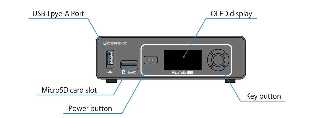
USB Tpye-A Port
USB Type-A port for connecting accessories for the Base Unit.
MicroSD card slot
MicroSD card slot used when updating the Base Unit firmware.
→ How to update the firmware
OLED display
The OLED display is used to show the operating status of the Base Unit. The menu is displayed during the settings using the buttons on the unit.
→ How to read the main status screen
Power button
This button is used to turn on or off the Base Unit.
→ How to boot the Base Unit
→ How to shut down the Base Unit
Key button
These key buttons are used when configuring the Base Unit, etc. There are four buttons (up, down, left, right) used to move the cursor and input values, as well as a OK button.
Rear
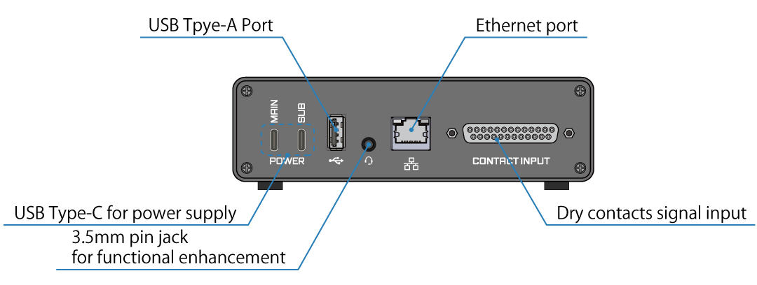
USB Type-C for power supply
These are for the power supplies for the Base Unit; two inputs, MAIN and SUB.
→ Supplying power to the Base Unit
USB Tpye-A Port
This is a USB Type-A terminal for connecting a video switcher that outputs tally control signals via a USB interface.
→ USB interface
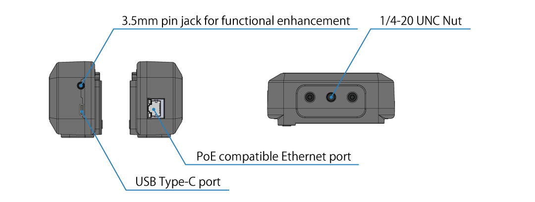
3.5mm pin jack for functional enhancement
Currently this is not used.
Ethernet port
An interface for connecting the Base Unit to the network, 1000BASE-TX Ethernet. This interface can also be used to connect a video switcher that outputs a tally control signal via an Ethernet interface.
→ Base Unit network settings
→ Ethernet interface
Dry contacts signal input
A terminal for connecting a video switcher that outputs a tally control signal via dry contacts contact output.
→ Dry contacts signal interface
→ Signal assignment
側面
1/4-20 UNC Nut
本製品を三脚等に取り付けるためのナットです(右側面)。
M4 nut
These nuts are used to secure this product.
Bottom
M3 nut
These nuts are used to secure this product to shelves, etc.
Lamp Unit
The names and functions of the part of Lamp Unit are shown in the figure below.
Front and rear
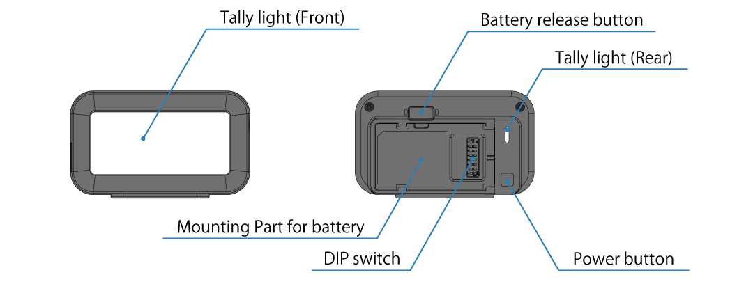
Tally light (Front)
This is the light-emitting part of the tally light and mainly for the performers to see.
Tally light (Rear)
This is the light-emitting part of the tally light and mainly for the camera operator to see. This lamp will also illuminate or flash to indicate certain conditions when the Lamp Unit is in, such as when the battery is low or waiting to connect to the Base Unit.
→ Rear tally light status information
Mounting Part for battery
This is for attaching the battery. This is used when powering the Lamp Unit from a battery.
→ Powering the Lamp Unit with a battery
Battery release button
This is a button to release the battery.
Power button
This is a button to turn the Lamp Unit on and off. It also allows to adjust the brightness of the lamp while it is in operation.
→ The priority of PoE power and USB power is undefined, and it will operate using either power. Using them together is not recommended.
→ Changing brightness
DIP switch
This DIP switch is used to set the lamp ID of the Lamp Unit. For models with wireless function, this DIP switch is also used to set whether or not the lamp operates as a wireless master Lamp Unit.
→ Lamp ID setting
→ Wireless master Lamp Unit settings
Side and bottum
USB Type-C port
This is a terminal for external power input. Use this when powering the Lamp Unit from a USB power source.
→ Powering from a USB power source
PoE compatible Ethernet port
This is a 100BASE-TX Ethernet interface to connect the Lamp Unit to a network. Also supports PoE power reception.
→ Connecting to Ethernet
→ Powering with PoE
3.5mm pin jack for functional enhancement
Currently this is not used.
1/4-20 UNC Nut
These nuts are to mount the Lamp Unit on a tripod.
How to set up and operate
You can change the settings of this product and operate various functions by using the key buttons on the front of the Base Unit, or by using the web application built into the Base Unit. The characteristics of each method are as follows, and you can use them according to the operation you want to perform.
Operation using the key buttons on the front of the Base Unit
Operation using the key buttons on the front of the Base Unit has the following features.
It can be used even when the product is not connected to a network (such as before initial setup).
There is no need to prepare external devices such as a computer for operation.
There are some functions that cannot be configured or operated using the buttons.
Therefore, it is suitable for simple configuration and operation.
Operation using FlexTally Pro Utility (web application)
Operation using the web application, FlexTally Pro Utility, has the following features.
To use the web application, the network settings for this product must be completed.
A separate device that can run a web browser, such as an operating PC, is required.
The web application allows you to operate all of the product’s functions.
Therefore, it is suitable for more advanced settings and operations.
4 Signals
This chapter explains the signals and their statuses used in the tally light system using this product.
Tally control signals
A tally control signal is a physical or logical signal output from a video switcher for the purpose of controlling a tally lamp. The Base Unit of this product operates by receiving the tally control signal.
Input numbers
The tally control signal outputs a signal which indicates the selection status of multiple video channels that can be input to the video switcher. In this device, to distinguish between these channels, a unique “input number” is assigned to each channel, and these are referenced by the input number.
When using dry contacts inputs, the input numbers are assigned the same as the point numbers, 1 to 16. However, when operating with three input states, “Not selected”, “Preview” and “Program”, the input numbers are assigned 1 to 8. When using other interfaces, the input numbers usually correspond to the video input numbers of the video switcher, but this may not be the case when using a software switcher, etc.
Input status
The tally control signal can have three states - “Not Selected,” “Preview,” or “Program” - independently for each channel.
Tally control signal physical interface
The physical interface that the video switcher uses to output the tally control signal varies depending on the video switcher model. The interfaces listed in the table below can be connected to the Base Unit of this product.
Please check the following that the models listed in the table below may be updated in the future. For the latest information, please check the compatible switcher list on the product page.
→ Compatible Switchers
Tally control signal physical interface |
Applicable Manufacturer/Model etc. |
|---|---|
Dry contacts inputs |
Common |
Ethernet port |
Blackmagic Design ATEM series, NewTek TriCaster series, Telestream Wirecast、StudioCoast PTY vMix |
USB |
Roland V-1HD/V-1SDI/VR-1HD/V-8HD/V-160HD/VR-6HD/VR-120HD etc. |
Dry contacts signal interface
For dry contacts signal signals, use a dedicated cable to connect to the tally input connector on the Base Unit. If the input status is operated in only two states, “Not selected” and “Program”, 16 channels can be input. If the input status is operated in three states, “Not selected”, “Preview” and “Program”, two points are used per channel, allowing eight channels to be input.
Connector
The type of connector on the Base Unit is a D-SUB 25-pin female. The compatible connector is a D-SUB 25-pin male.
Signal assignment
Signal assignment is as shown in the table below.
If the input mode is set to 16 channels of program only, input numbers 1 to 16 are assigned one contact each, and when a contact is made, the corresponding input number is recognized as being in the program state. If the input mode is set to 8 channels of program/preview, input numbers 1 to 8 are assigned two contacts each, and depending on which contact is made, the corresponding input number is recognized as being in the program or preview state.
Pin |
I/O |
Description |
Input Number (PGM Only) |
Input Number (PGM/PVW) |
|---|---|---|---|---|
1 |
NC |
|||
2 |
INPUT |
IN 1 |
1 PGM |
1 PGM |
3 |
INPUT |
IN 2 |
2 PGM |
2 PGM |
4 |
INPUT |
IN 3 |
3 PGM |
3 PGM |
5 |
INPUT |
IN 4 |
4 PGM |
4 PGM |
6 |
INPUT |
IN 5 |
5 PGM |
5 PGM |
7 |
INPUT |
IN 6 |
6 PGM |
6 PGM |
8 |
INPUT |
IN 7 |
7 PGM |
7 PGM |
9 |
INPUT |
IN 8 |
8 PGM |
8 PGM |
10 |
COMMON |
GND |
||
11 |
I/O |
RS485 A (+) |
||
12 |
NC |
|||
13 |
OUTPUT |
+5V |
||
14 |
COMMON |
GND |
||
15 |
INPUT |
IN 9 |
9 PGM |
1 PVW |
16 |
INPUT |
IN 10 |
10 PGM |
2 PVW |
17 |
INPUT |
IN 11 |
11 PGM |
3 PVW |
18 |
INPUT |
IN 12 |
12 PGM |
4 PVW |
19 |
INPUT |
IN 13 |
13 PGM |
5 PVW |
20 |
INPUT |
IN 14 |
14 PGM |
6 PVW |
21 |
INPUT |
IN 15 |
15 PGM |
7 PVW |
22 |
INPUT |
IN 16 |
16 PGM |
8 PVW |
23 |
COMMON |
GND |
||
24 |
I/O |
RS485 B (-) |
||
25 |
NC |
The RS485 signal is for expansion purposes and cannot be used in the current version.
Electrical specifications
The tally inputs (IN 1 to IN 16) are dry contact signal inputs. Relay, open drain, open collector, and other outputs can be connected. Voltage outputs cannot be connected as this may cause a malfunction.
Item |
unit |
min value |
standard value |
max value |
measurement conditions |
|---|---|---|---|---|---|
Maximum switching voltage |
V |
0 |
3.0 |
3.2 |
INPUT-COMMON間 |
Input voltage *1 |
V |
— |
— |
12 |
INPUT-COMMON間 |
Input current |
mA |
— |
10 |
— |
INPUT-COMMON short circuit |
*1 Maximum voltage allowed when performing external pull-up, etc.
Equivalent circuit diagram
The equivalent circuit diagram for non-voltage contact signal input is shown below.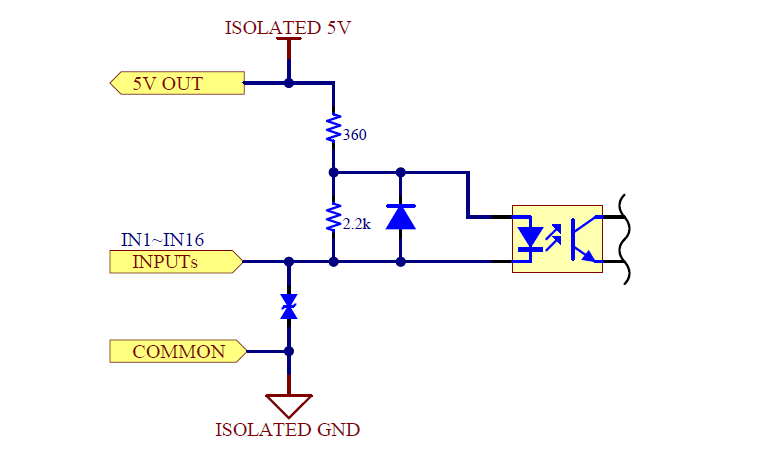
Ethernet interface
In the case of Ethernet, the Ethernet interfaces of the video switcher and the Base Unit are connected to the same network and communicate via IPv4.There is no limit to the number of logical channels that can be input, and the value output by the video switcher is used as the input number.
USB interface
In the case of USB, a USB cable is used to physically connect the video switcher and the Base Unit. There is no limit to the number of logical channels that can be input, and the value output by the video switcher is used as the input number.
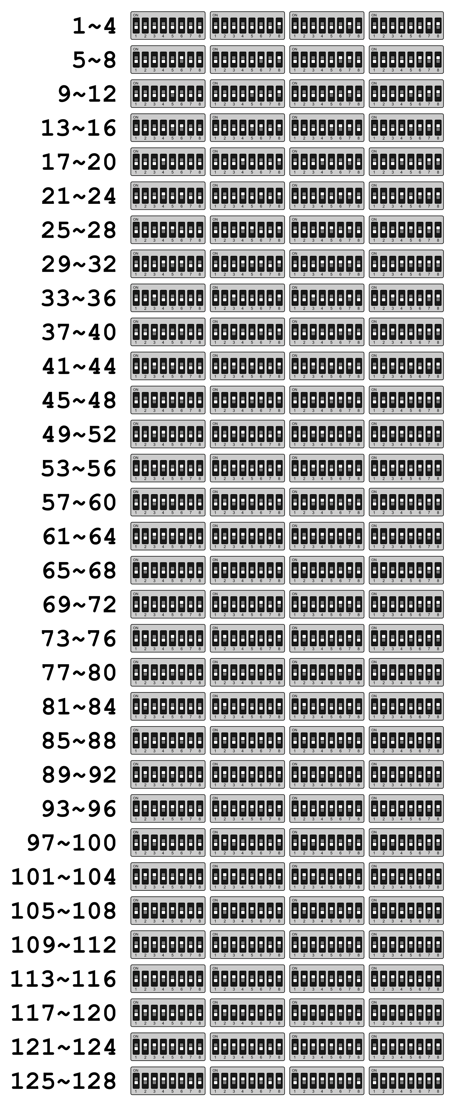
Lamp ID
The lamp ID is a number used by the Base Unit to distinguish between lamps connected to the system, and can range from 1 to 128. Lamp behavior can be defined for each lamp ID.
A Lamp Unit always has one lamp ID as a setting value for which lamp ID it will behave. The lamp ID of a Lamp Unit can be set using the DIP switch on the rear side of the Lamp Unit.
It is also possible to have multiple Lamp Units with the same lamp ID set in one system. In this case, these Lamp Units will behave in the same way in parallel. There is no limit to the number of Lamp Units with the same lamp ID that can be connected.
Restrictions on lamp IDs of Lamp Units connected wirelessly
When using the wireless connection function between Lamp Units, there are restrictions on the lamp IDs that can be used. Only 16 lamp IDs selected from the following range (can be set on the Base Unit) and can be transmitted wirelessly.
1 ~ 16
17 ~ 32
33 ~ 48
49 ~ 64
65 ~ 80
81 ~ 96
97 ~ 112
113 ~ 128
Therefore, the lamp ID set for the Lamp Unit that will be used as a wireless client must be a value within the selected range.
If you use both wireless and wired connections at the same time, this restriction does not apply to Lamp Units connected via wired. For example, if the range of lamp IDs for wireless transmission is set to 1 to 16, the lamp IDs 1 and 16 can operate as wireless client devices, but the lamp ID 17 cannot. However, if you connect a Lamp Unit via Ethernet, lamp ID 17 can also be used.
Mapping
Mapping is information that defines how a lamp ID changes when a certain input number changes to a certain input state. Mapping allows you to determine the behavior of a certain lamp ID for a certain input number.
Default mapping
The following mapping is set as the default value when this product is shipped from the factory. The default mapping is the same regardless of the physical interface of the tally control signal.
Input numbers |
Input status |
Lamp ID |
Lighting color |
|---|---|---|---|
1 |
Program |
1 |
Red |
Preview |
1 |
Green |
|
2 |
Program |
2 |
Red |
Preview |
2 |
Green |
|
3 |
Program |
3 |
Red |
Preview |
3 |
Green |
|
4 |
Program |
4 |
Red |
Preview |
4 |
Green |
|
5 |
Program |
5 |
Red |
Preview |
5 |
Green |
|
6 |
Program |
6 |
Red |
Preview |
6 |
Green |
|
7 |
Program |
7 |
Red |
Preview |
7 |
Green |
|
8 |
Program |
8 |
Red |
Preview |
8 |
Green |
|
9 |
Program |
9 |
Red |
Preview |
9 |
Green |
|
10 |
Program |
10 |
Red |
Preview |
10 |
Green |
|
11 |
Program |
11 |
Red |
Preview |
11 |
Green |
|
12 |
Program |
12 |
Red |
Preview |
12 |
Green |
|
13 |
Program |
13 |
Red |
Preview |
13 |
Green |
|
14 |
Program |
14 |
Red |
Preview |
15 |
Green |
|
15 |
Program |
15 |
Red |
Preview |
15 |
Green |
|
16 |
Program |
16 |
Red |
Preview |
16 |
Green |
5 Installation
This chapter explains the installation method for using this product.
Installing and powering the Base Unit
First, install and power the Base Unit of this product. The tally signal output of the video switcher must be connected to the Base Unit. For this reason, we recommend that you install the Base Unit near the video switcher.
Connecting to a video switcher
The Base Unit operates by receiving a tally control signal from the video switcher. Connect the Base Unit and video switcher.
You can select the physical interface for connecting the video switcher and the Base Unit from dry contact signal (GPIO), Ethernet, or USB.
→ Tally control signal physical interface
When making a GPIO connection, connect the dry contact signal input on the rear, when making a USB connection, connect the USB Type-A port on the rear, and when making an Ethernet connection, connect the Ethernet connector on the rear to the corresponding connector on the video switcher (or the computer on which it is installed a software switcher) with the appropriate cable.
→ Rear
Tip
We sell a variety of GPIO cables used to connect to video switchers. We can also make and sell semi-customized cables.
→ Do you sell GPIO cables?
→ Can Cerevo manufacture and sell GPIO cables for models that are not listed in the cable sales list?
Connecting to Ethernet
Connect the Base Unit’s Ethernet port to an Ethernet switch (sold separately) to configure the tally light system described below using a LAN cable (sold separately).
If you are connecting to a video switcher via Ethernet, connect the video switcher and peripheral devices to the Ethernet switch as well.
Supplying power to the Base Unit
Next, supply power to the Base Unit. The Base Unit runs on USB Type-C power and can be powered by a commercially available AC adapter or power bank, etc., provided that it meets all of the following requirements, in addition to the AC adapter (CDP-ADP05A) specified by us.
The power output terminal is USB Type-C type.
It can supply up to 2.0 amps of current at DC 5 volts.
It complies with the USB Power Delivery standard.
Even if the power supply complies with USB Power Delivery and can supply more than 10 watts, it cannot be used if it cannot output 2.0 amps at 5 volts. Please check the instruction manual and nameplate of the power supply before use.
The Base Unit has two power input terminals, MAIN and SUB. When using a single power supply, connect the power supply unit specified in this manual to MAIN. When using dual power supply, connect both MAIN and SUB to the power supply unit. When connecting the Base Unit to a power supply unit, be sure to use a cable with a current resistance of 2.0 amps or more and USB Type-C connectors on both ends.
When using dual power supply, also refer to the section on power supply redundancy.
→ Power supply redundancy
Power supply redundancy
By connecting different power supplies to the MAIN and SUB power input terminals at the same time, the power supply to the Base Unit can be made redundant. When both systems are receiving power, the Base Unit will give priority to receiving power from the MAIN side, and if the power supply from the MAIN side is interrupted, it will switch to receiving power from the SUB side and continue operating. Also, if power is supplied to the MAIN side while receiving power from the SUB side, the power receiving will be switched from SUB to MAIN and operation will continue.
Power switching is performed without interruption, and hot swapping of power supplies is also possible. However, depending on the power receiving status of the Base Unit and the power supply capacity, a power interruption may occur during switching. Please perform sufficient verification when operating power redundancy and hot swapping.
Tip
Depending on the model, a power bank may be equipped with an auto power off function that automatically turns off the power if the battery is left unloaded for a certain period of time.
How to boot the Base Unit
The Base Unit will start up automatically when you connect the power supply (there is no need to press the power button). When the startup starts, the Cerevo logo will appear, the display will go dark for a few seconds, and then the FlexTally Pro logo will appear, and the Base Unit will enter its final operating state. It is not a malfunction if the display goes dark during startup.
Before starting the Base Unit, make sure that the network interface and video switcher are connected and started up. In the case of a software switcher, make sure that the computer which is the software is installed and connected, and the software is started up. If you start the Base Unit before making these connections, it may not operate correctly.
How to shut down the Base Unit
When the Base Unit is on, press and hold the power button on the front and a menu will appear on the display to shut down and restart the Base Unit.
If you select Power Off, the product will perform the shutdown process and the power will be turned off.
If you select Reboot, the product will reboot.
If you unplug the power without first shutting down the Base Unit, configuration data and other data stored in the Base Unit may be corrupted or lost.
Video switcher connection settings
Configure the connection settings between the Base Unit and the video switcher. GPIO is selected as the connection interface with the video switcher in the factory default setting. To change to a connection method other than GPIO, follow the procedure below. Connection settings can be made from the web application or the main unit UI.
Tip
If the Base Unit and video switcher are not connected properly, please check the following troubleshooting steps.
→ I can not connect the Base Unit and my switcher.
Connecting to Blackmagic Design ATEM switcher
When connecting to ATEM, first check the IP address of the ATEM unit.
Tip
You can check the IP address in “ATEM Setup” or on the ATEM’s unit display. The method for checking the IP address of the ATEM varies depending on the model. Please refer to the ATEM manual for specific instructions.
Using the web application for the settings
Use an Ethernet switch (sold separately) to connect the operation computer etc. to the same IPv4 subnet as the Base Unit.
Start any browser on the operation computer etc.
Boot the video switcher.
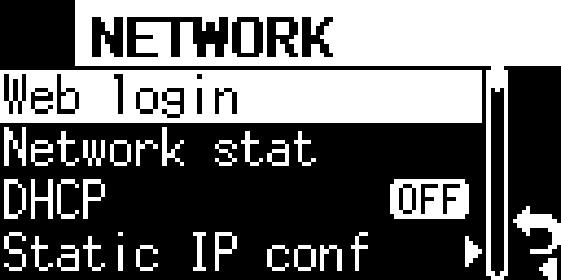
Boot the Base Unit, press the Confirm button on the main status screen to open the main menu, and select “Network”.

Select “Web login” in the Network menu.
表示されているURLを、ブラウザのURL欄に入力してください。

If the connection is successful, the FlexTally Pro web application will be displayed in the browser.
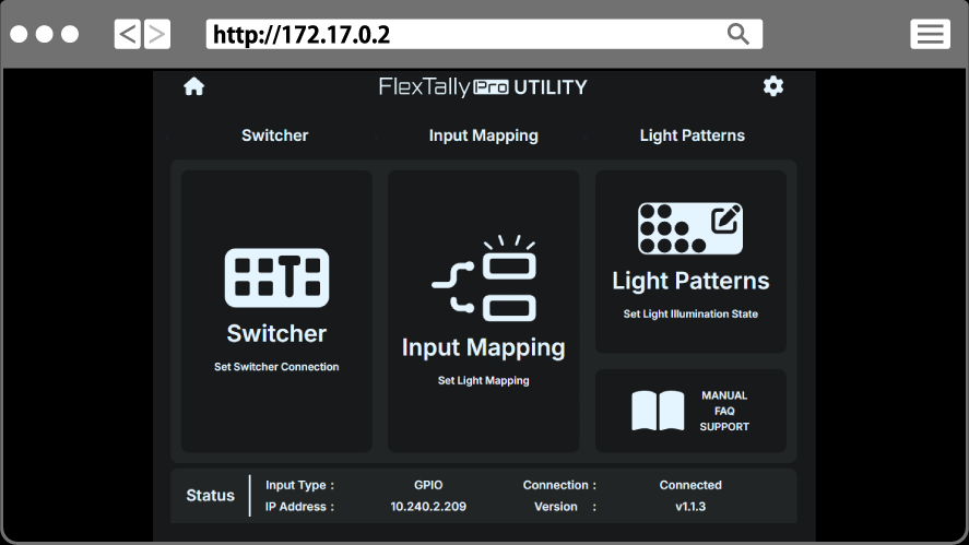
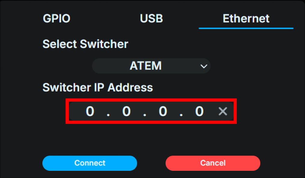
Select “Switcher”.
Click the “Change Settings” button on the left side of the screen to display the settings dialog box.
Select the “Ethernet” tab at the top of the dialog box.
Select “ATEM” from the “Select Switcher” pull-down menu.
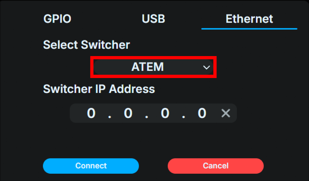
Enter the IP address of the ATEM unit in the “Enter switcher IP address” field.
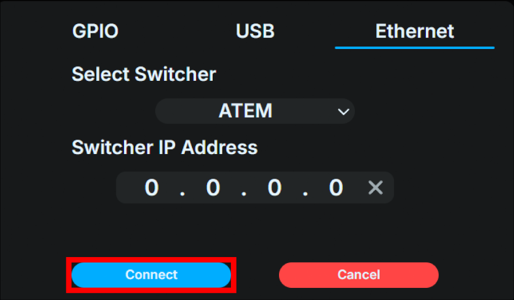
Click the “Connect” button to connect to the switcher you have set up.
Using the Base Unit UI for the settings
Boot the video switcher.
Turn on the Base Unit, and press the confirm button on the main status screen to open the main menu, then select “Switcher.”

Select “Interface”.
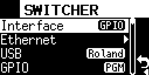
Select “Ethernet”. After making the selection, press the confirm button again to return to the “Switcher” menu.

Select “Ethernet” in the “Switcher” menu.

Select “ATEM”.

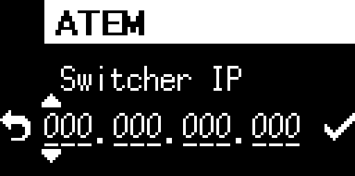
Enter the IP address of the ATEM unit into the entry field displayed using the front operation buttons. After entering the address, select the “check mark” on the right to save the information entered and return to the “Switcher” menu.
Once the setup is complete, proceed to the “Switcher” menu and attempt to connect to the switcher you have set up.
Connecting to Vizrt (NewTek) TriCaster switcher
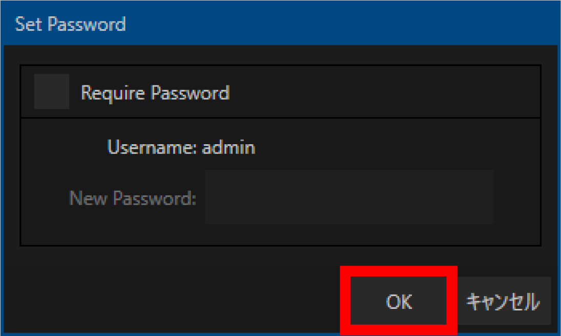
To connect to TriCaster, you must first unlock the TriCaster password using the following procedure.
Open the TriCaster main page and select “Administrator Mode” from the “Shutdown” menu.
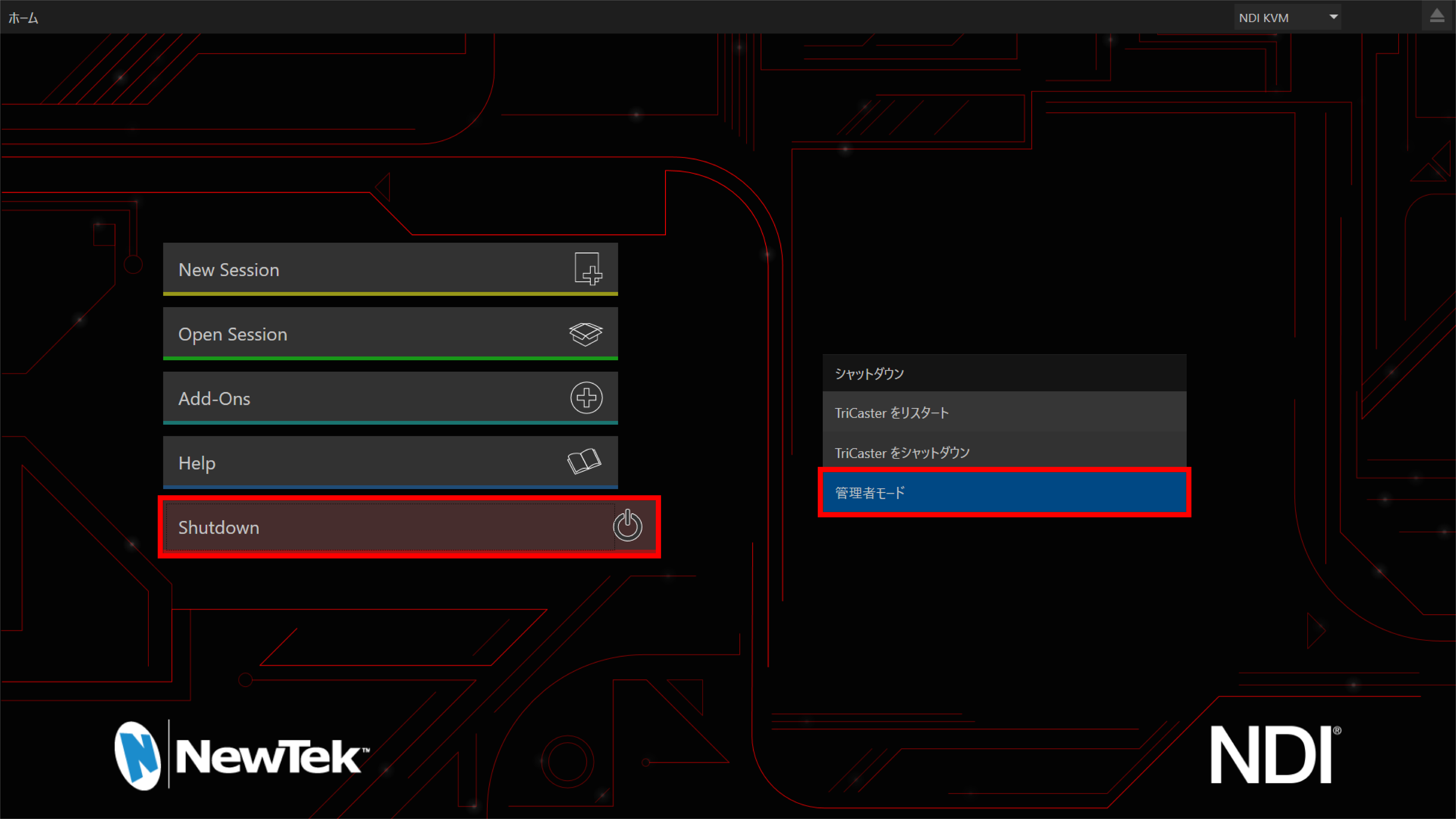
Select “Set LivePanel Password”.
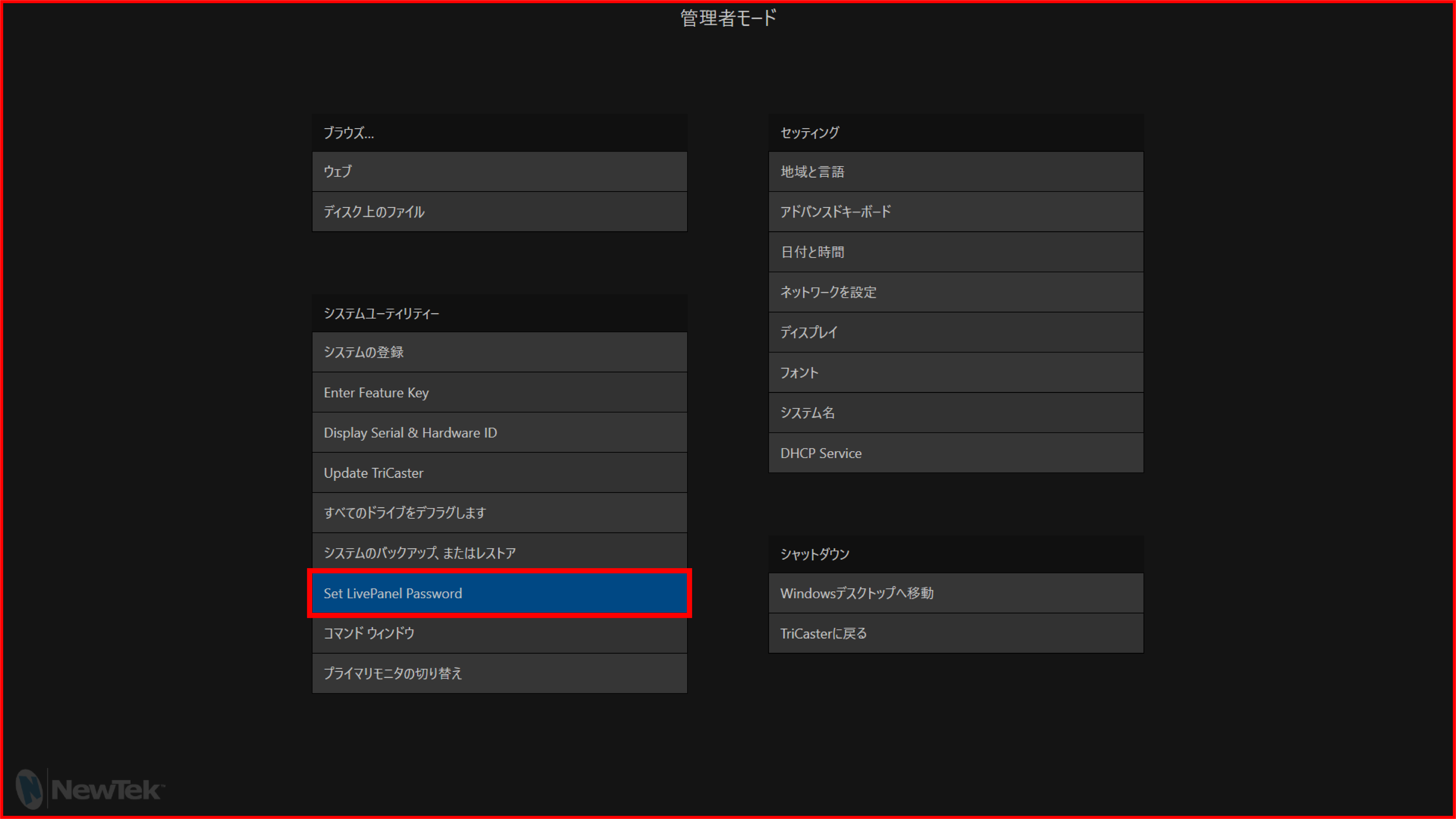
Uncheck “Require Password” in the “Set Password” window that appears.
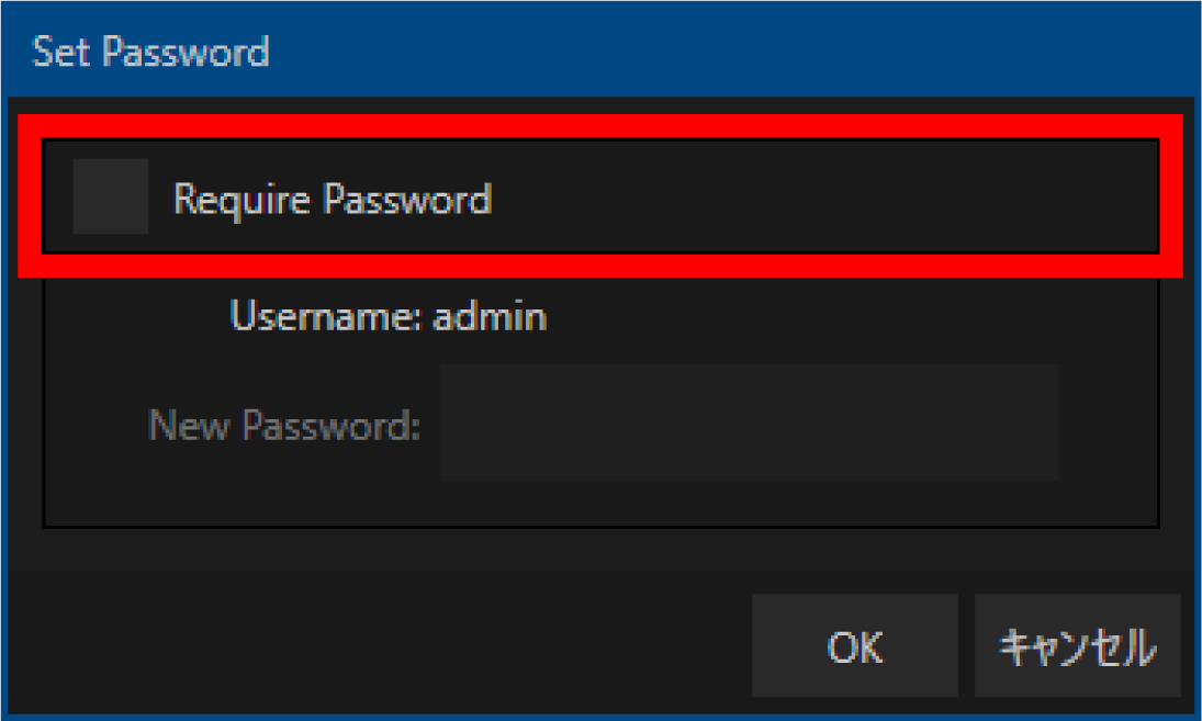
Click “OK”.
Next, follow the steps below to find the IP address of the TriCaster unit.
Select “Go to Windows Desktop” in “Administrator Mode”.
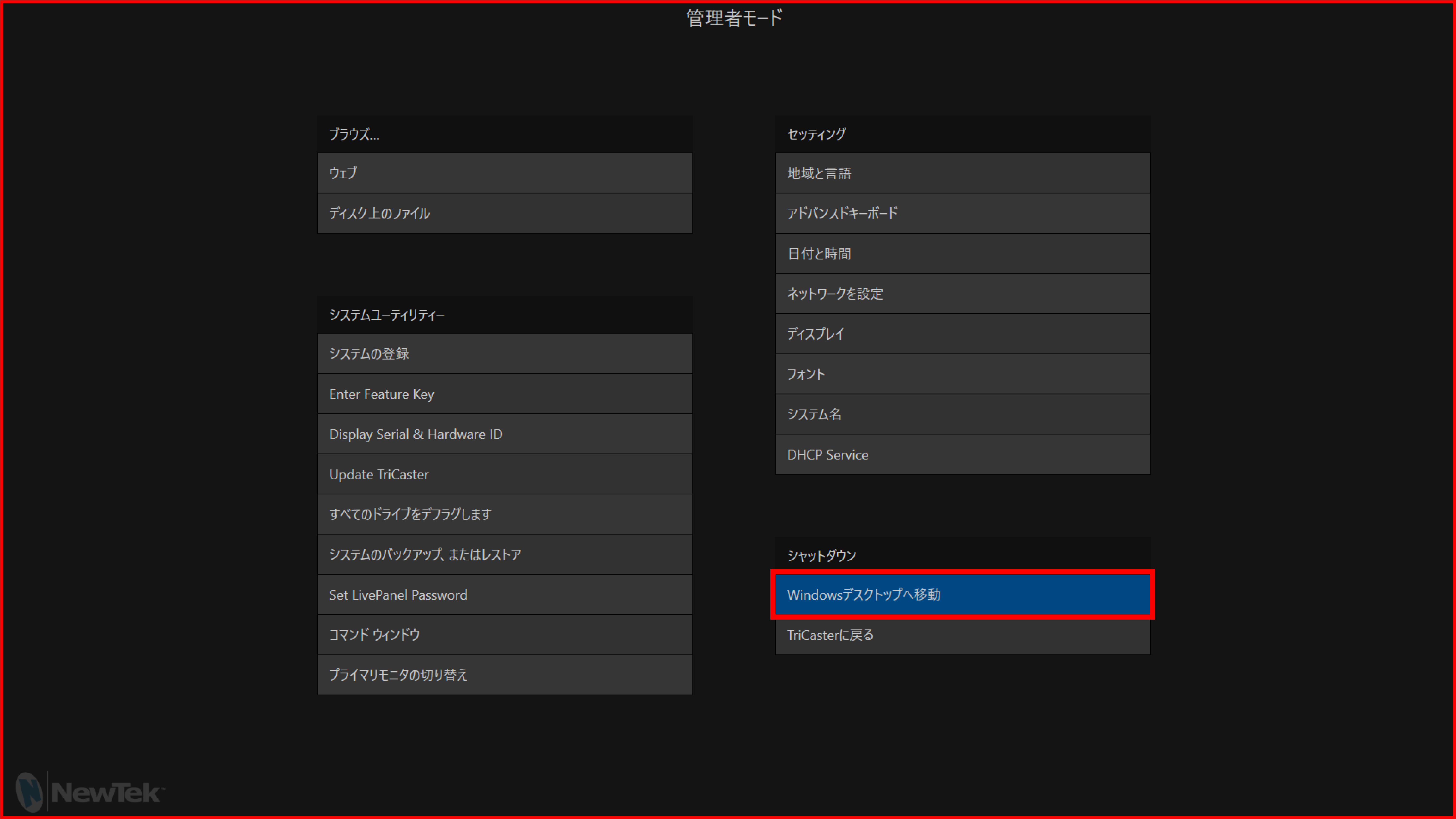
Open “Control Panel” → “Network and Internet” → “Network and Sharing Center” → “Change adapter settings” and check the IP address from the properties of the Ethernet connected to the network.
Using the web application for the settings
Use an Ethernet switch (sold separately) to connect the operation computer etc. to the same IPv4 subnet as the Base Unit. This step is not necessary if you configure the settings using a browser installed on the TriCaster unit itself.
Start any browser on the operation computer etc.
Boot the Base Unit, press the Confirm button on the main status screen to open the main menu, and select “Network”.
Select “Web login” in the Network menu.
表示されているURLを、ブラウザのURL欄に入力してください。
If the connection is successful, the FlexTally Pro web application will be displayed in the browser.
Select “Switcher”.
Click the “Change Settings” button on the left side of the screen to display the settings dialog box.
Select the “Ethernet” tab at the top of the dialog box.
Select “TriCaster A” or “TriCaster B” from the “Select Switcher” pull-down menu.
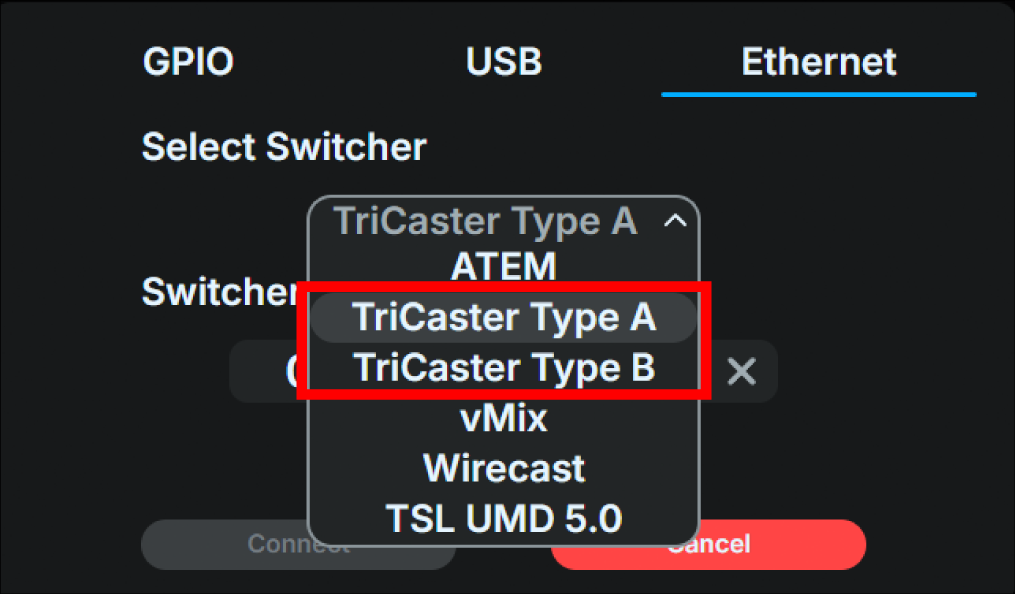
If you are using TriCaster version 8.4 or later, select “TriCaster Type B”.
Otherwise, first try “TriCaster Type A”. If it does not work, try again with “TriCaster Type B”.
Tip
For TriCaster connections, please also refer to the troubleshooting guide. → Issues Regarding Connectivity with TriCaster
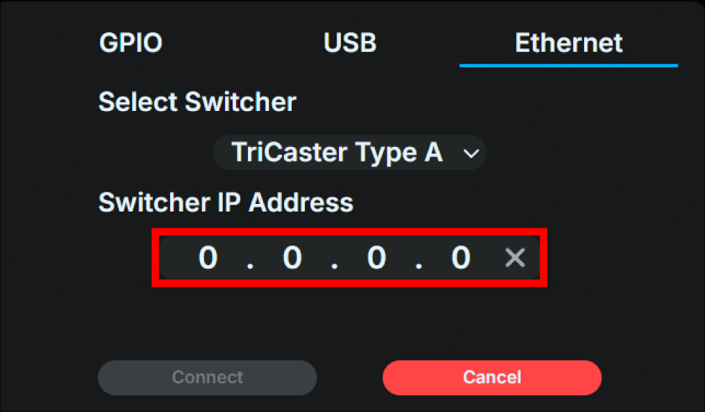
Enter the IP address of the TriCaster unit in the “Enter switcher IP address” field.
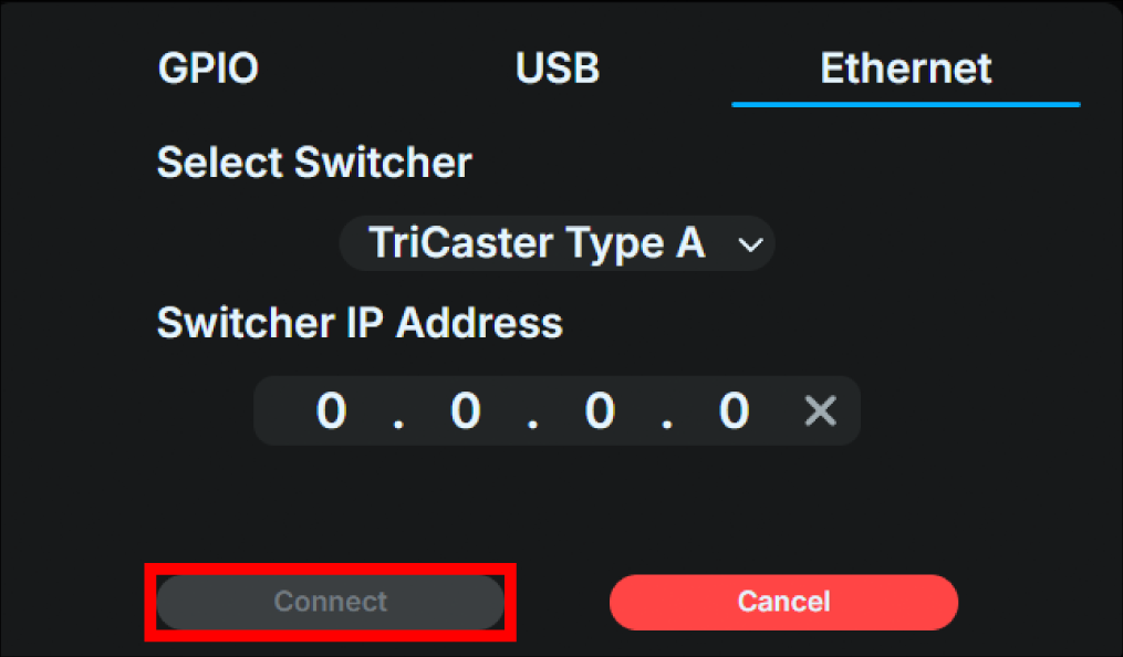
Click the “Connect” button to connect to the switcher you have set up.
Using the Base Unit UI for the settings
Turn on the Base Unit, and press the confirm button on the main status screen to open the main menu, then select “Switcher.”
Select “Interface”.
Select “Ethernet”. After making the selection, press the confirm button again to return to the “Switcher” menu.
Select “Ethernet” in the “Switcher” menu.
Slect “TriCaster Type A” or “TriCaster Type B”.
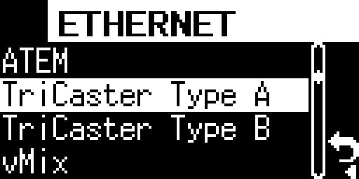
If you are using TriCaster version 8.4 or later, select “TriCaster Type B”.
Otherwise, first try “TriCaster Type A”. If it does not work, try again with “TriCaster Type B”.
Tip
For TriCaster connections, please also refer to the troubleshooting guide. → Issues Regarding Connectivity with TriCaster
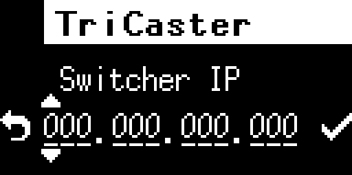
Enter the IP address of the TriCaster into the entry field displayed using the front operation buttons. After entering the address, select the “check mark” on the right to save the information entered and return to the “Switcher” menu.
Once the setup is complete, proceed to the “Switcher” menu and attempt to connect to the switcher you have set up.
Connecting to Roland switcher
Using the web application for the settings
Use an Ethernet switch (sold separately) to connect the operation computer etc. to the same IPv4 subnet as the Base Unit.
Start any browser on the operation computer etc.
Boot the video switcher.
Boot the Base Unit, press the Confirm button on the main status screen to open the main menu, and select “Network”.
Select “Web login” in the Network menu.
表示されているURLを、ブラウザのURL欄に入力してください。
If the connection is successful, the FlexTally Pro web application will be displayed in the browser.
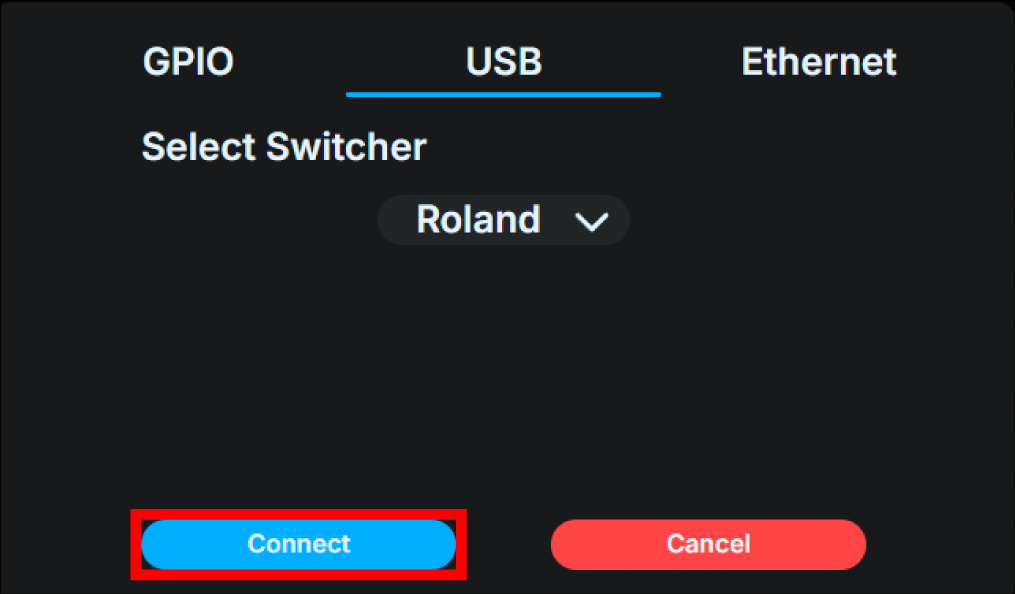
Select “Switcher”.
Click the “Change Settings” button on the left side of the screen to display the settings dialog box.
Select the “USB” tab at the top of the dialog box.
Select “Roland” from the “Select Switcher” pull-down menu.
.Click the “Connect” button to connect to the switcher you have set up.
Using the Base Unit UI for the settings
Boot the video switcher.
Turn on the Base Unit, and press the confirm button on the main status screen to open the main menu, then select “Switcher.”
Select “Interface”.
Select “USB”. After making the selection, press the confirm button again to return to the “Switcher” menu.

Select “USB” in the “Switcher” menu.
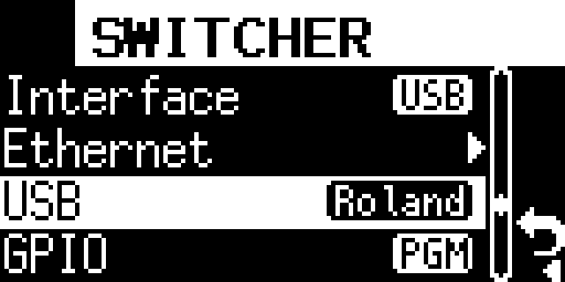
Select “Roland”. After making the selection, press the confirm button again to return to the “Switcher” menu.

Once the setup is complete, proceed to the “Switcher” menu and attempt to connect to the switcher you have set up.
Connecting to vMix
When connecting to vmIX, first check the IP address of the vMix.
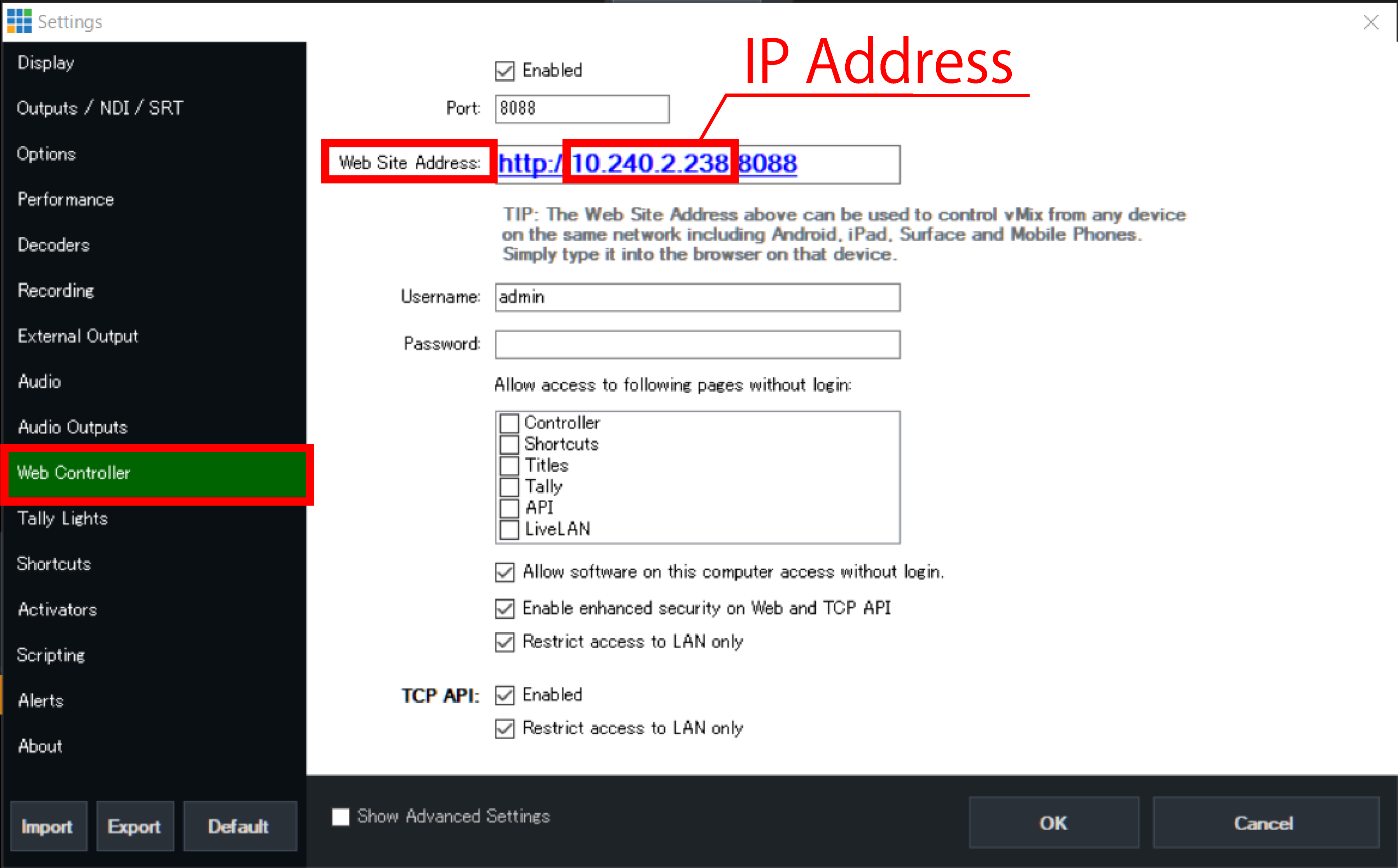
Start vMix, select “Setting”.
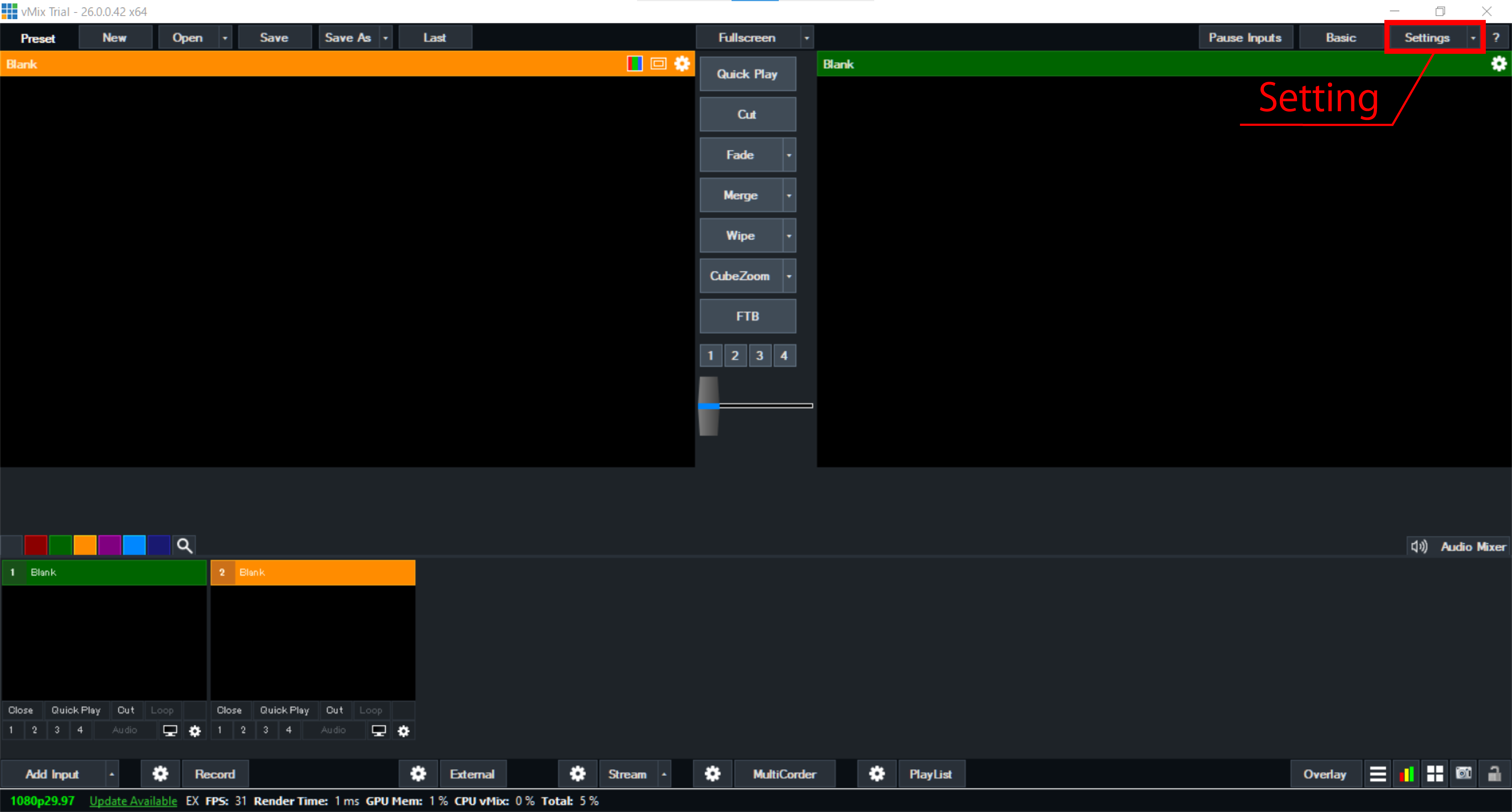
Select “Web Controller”, check the IP address displayed in “Web Site Address”.
Using the web application for the settings
.Use an Ethernet switch (sold separately) to connect the operation computer etc. to the same IPv4 subnet as the Base Unit. This step is not necessary if you configure the settings using a browser installed on the vMix itself.
Start any browser on the operation computer etc.
Boot the Base Unit, press the Confirm button on the main status screen to open the main menu, and select “Network”.
Select “Web login” in the Network menu.
表示されているURLを、ブラウザのURL欄に入力してください。
If the connection is successful, the FlexTally Pro web application will be displayed in the browser.
Select “Switcher”.
Click the “Change Settings” button on the left side of the screen to display the settings dialog box.
Select the “Ethernet” tab at the top of the dialog box.
Select “vMix” from the “Select Switcher” pull-down menu.
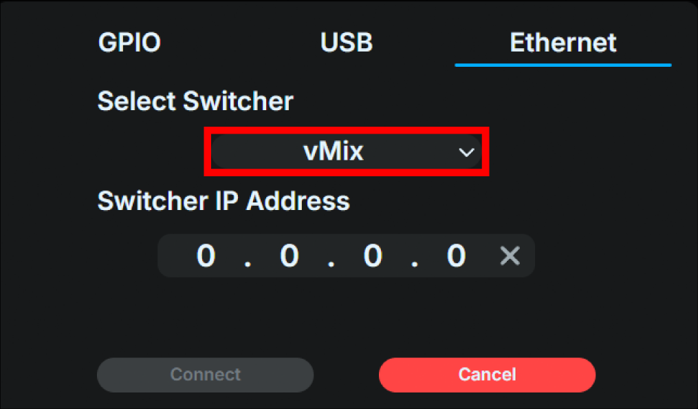
Enter the IP address of the vMix unit in the “Enter switcher IP address” field.
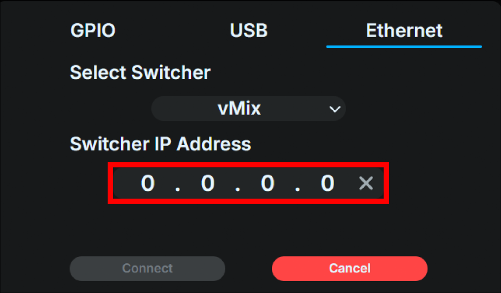
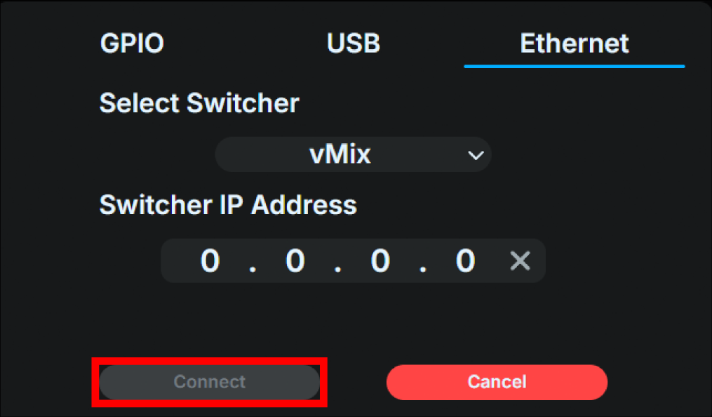
Click the “Connect” button to connect to the switcher you have set up.
Using the Base Unit UI for the settings
Turn on the Base Unit, and press the confirm button on the main status screen to open the main menu, then select “Switcher.”
Select “Interface”.
Select “Ethernet”. After making the selection, press the confirm button again to return to the “Switcher” menu.
Select “Ethernet” in the “Switcher” menu.
Select “vMix”.

Enter the IP address of the vMIX into the entry field displayed using the front operation buttons. After entering the address, select the “check mark” on the right to save the information entered and return to the “Switcher” menu.
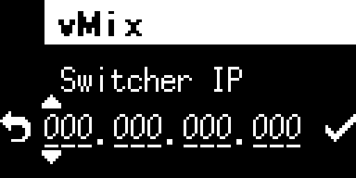
Once the setup is complete, proceed to the “Switcher” menu and attempt to connect to the switcher you have set up.
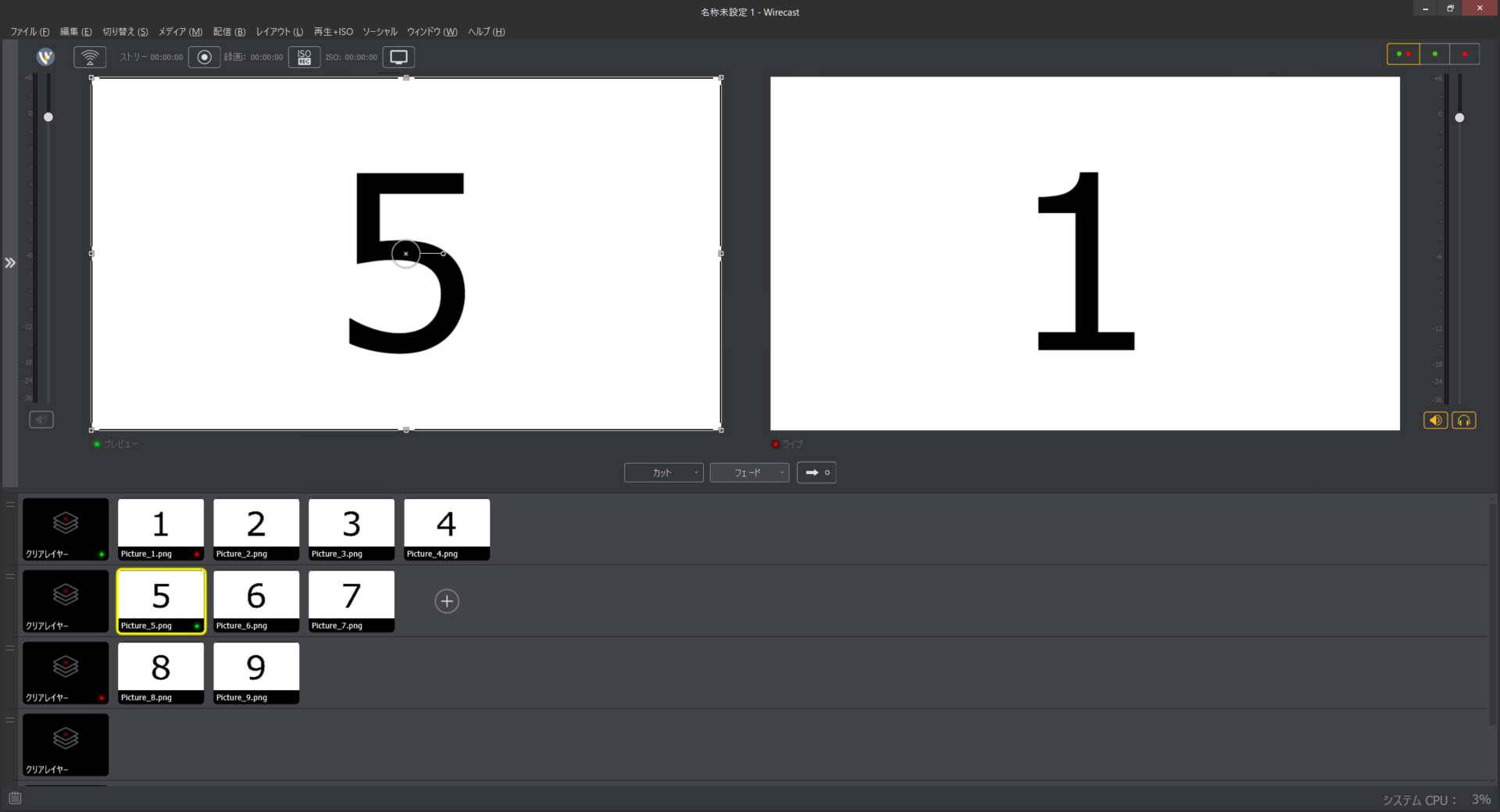
Connecting to Wirecast
To connect to the Wirecast switcher, first download “FlexTally For Wirecast” from the link below and install it on the computer running Wirecast.
Supported OS: Windows 10
PC requirements: 2GB or more of memory, 100MB or more of free space required for installation.
Next, check the IP address of the computer on which Wirecast is installed.
Using the web application for the settings
Use an Ethernet switch (sold separately) to connect the operation computer etc. to the same IPv4 subnet as the Base Unit. This step is not necessary if you configure the settings using a browser installed on the Wirecast unit itself.
Start any browser on the operation computer etc.
Boot the Base Unit, press the Confirm button on the main status screen to open the main menu, and select “Network”.
Select “Web login” in the Network menu.
表示されているURLを、ブラウザのURL欄に入力してください。
If the connection is successful, the FlexTally Pro web application will be displayed in the browser.
Select “Switcher”.
Click the “Change Settings” button on the left side of the screen to display the settings dialog box.
Select the “Ethernet” tab at the top of the dialog box.
Select “Wirecast” from the “Select Switcher” pull-down menu.
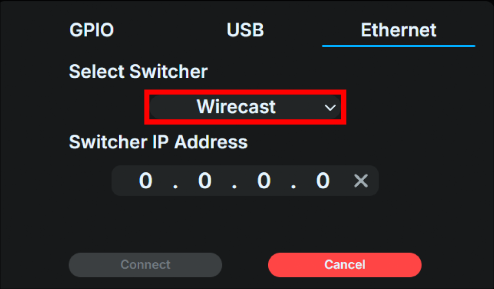
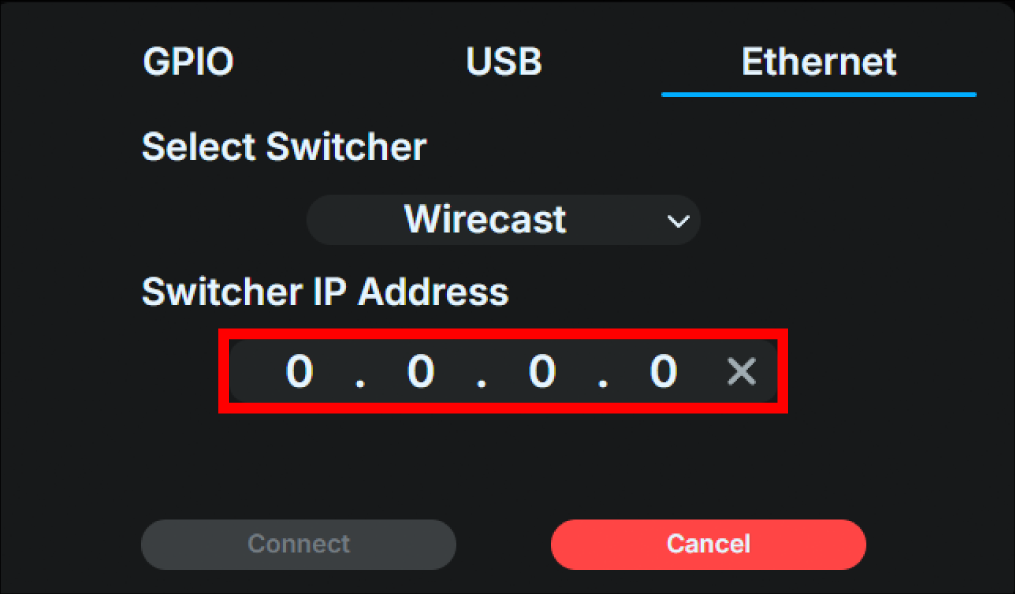
Enter the IP address of the Wirecast unit in the “Enter switcher IP address” field.
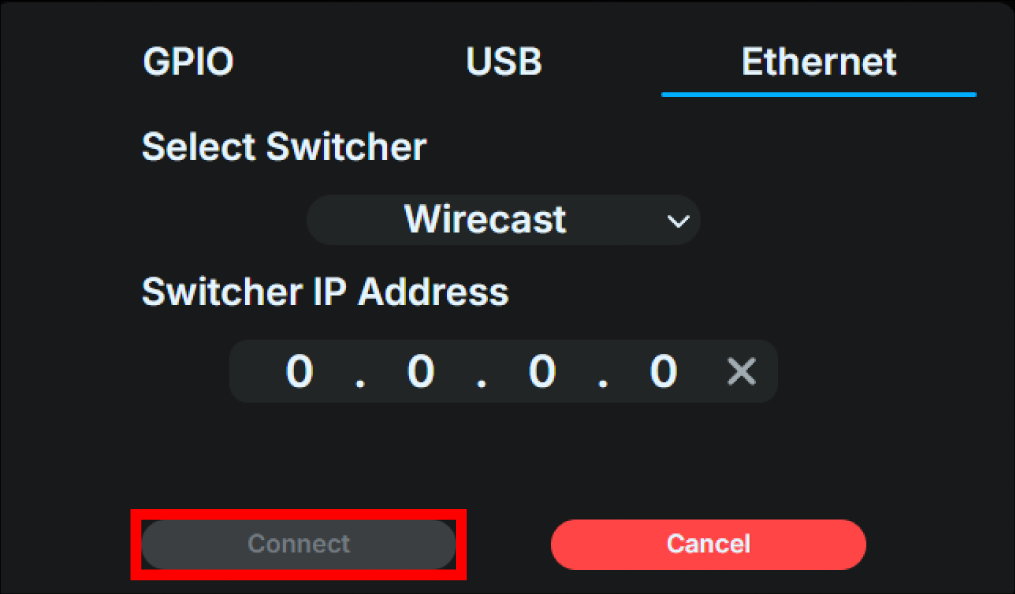
Click the “Connect” button to connect to the switcher you have set up.
For Wirecast switcher, additional settings for the Lamp Unit are required using “FlexTally For Wirecast”.
→ Lamp Unit settings with Wirecast
Using the Base Unit UI for the settings
Turn on the Base Unit, and press the confirm button on the main status screen to open the main menu, then select “Switcher.”
Select “Interface”.
Select “Ethernet”. After making the selection, press the confirm button again to return to the “Switcher” menu.
Select “Ethernet” in the “Switcher” menu.
Select “Wirecast”.

Enter the IP address of the vMix into the entry field displayed using the front operation buttons. After entering the address, select the “check mark” on the right to save the information entered and return to the “Switcher” menu.

Once the setup is complete, proceed to the “Switcher” menu and attempt to connect to the switcher you have set up.
For Wirecast switcher, additional settings for the Lamp Unit are required using “FlexTally For Wirecast”.
→ Lamp Unit settings with Wirecast
Connecting to a TSL UMD 5.0 compatible switcher
When connecting to a switcher that supports the TSL UMD 5.0 protocol, first set the Base Unit’s IP address on the switcher. Also, check the switcher’s TSL UMD 5.0 destination port, which port the switcher sends the signal to the Base Unit.
For the Base Unit’s IP address, refer to Base Unit network settings
For information on how to set the switcher and check the destination port, refer to the switcher manual.
Using the web application for the settings
Use an Ethernet switch (sold separately) to connect the operation computer etc. to the same IPv4 subnet as the Base Unit.
Start any browser on the operation computer etc.
Boot the Base Unit, press the Confirm button on the main status screen to open the main menu, and select “Network”.
Select “Web login” in the Network menu.
表示されているURLを、ブラウザのURL欄に入力してください。
If the connection is successful, the FlexTally Pro web application will be displayed in the browser.
Select “Switcher”.
Click the “Change Settings” button on the left side of the screen to display the settings dialog box.
Select the “Ethernet” tab at the top of the dialog box.
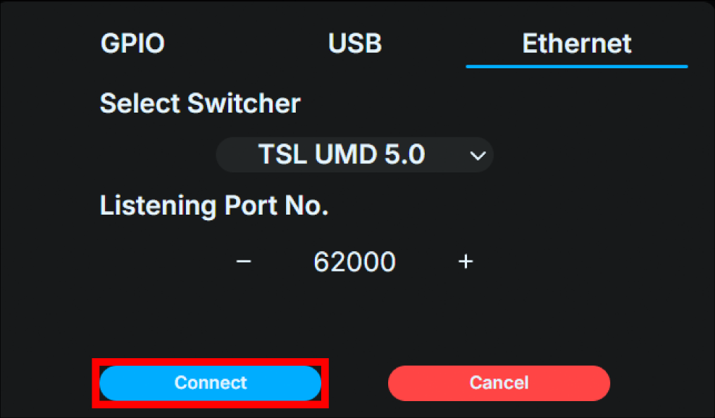
Select “TSL UMD 5.0” from the pull-down menu under “Select Switcher”.
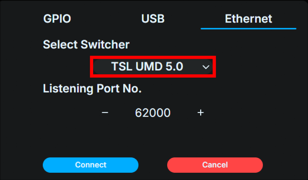
Enter the switcher’s TSL 5.0 destination port number in the “Listen Port No.” field.
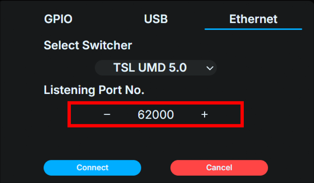
Click the “Connect” button to begin listening on the configured port.
Using the Base Unit UI for the settings
Turn on the Base Unit, and press the confirm button on the main status screen to open the main menu, then select “Switcher.”
Select “Interface”.
Select “Ethernet”. After making the selection, press the confirm button again to return to the “Switcher” menu.
Select “Ethernet” in the “Switcher” menu.
Select “TSL UMD 5.0”.

By using the front panel keys, enter the switcher’s TSL 5.0 destination port in the input field. After entering the information, select the check mark on the right to save the information and return to the “Switcher” menu.
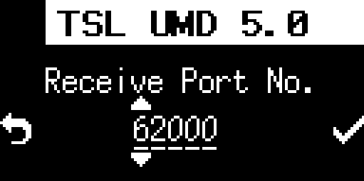
Once the setup is complete, the “Switcher” menu will begin listening on the configured port.
Lamp Unit installation and power supply
Lamp Unit installation
The Lamp Unit should be installed on top of the camera that will display the tally. It can be mounted using the tripod nut on the bottom. Necessary fittings must be prepared separately.
Tip
We recommend that you install the wireless master Lamp Unit in a high location with as good a view as possible from the wireless client Lamp Units.
→ The Lamp Unit’s wireless connection is lost.
Lamp ID setting
Set the lamp ID used by the Lamp Unit using the DIP switch on the back. For the correspondence between lamp ID and DIP switch, refer to the appendixDIP Switch Lamp ID Setting Table DIP switch lamp ID setting table. The lamp ID DIP switch setting must be done before turning on the power, and will not be reflected if it is changed while the power is on.
Tip
For information on how to assign a lamp ID, please refer to the chapter on Lamp ID. For simpler use, please use the lamp IDs listed in the default mapping tableDefault mapping.
Wireless master Lamp Unit settings
Lamp Units equipped with wireless functionality can function as wireless master Lamp Unit by changing the DIP switch settings. To function as a wireless master Lamp Unit, set DIP switch number 1 to ON. The settings of DIP switches 2 to 8 do not affect the operation of this function.
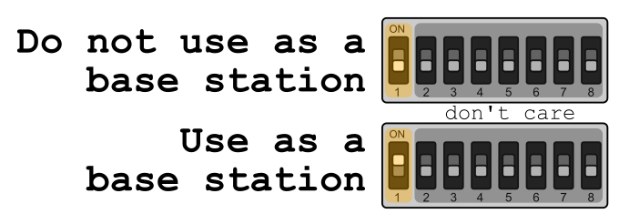
A Lamp Unit that will be used as a wireless master must be connected to the Base Unit via Ethernet. Even if the Lamp Unit is connected via Ethernet, if it is not to function as a wireless master or if it is to be used as a wireless client Lamp Unit, set DIP switch number 1 to OFF. This setting must be made before turning on the power, and will not be reflected if it is changed while the power is on.
Tip
There are restrictions on the lamp IDs that can be used for wireless connections.
→ Restrictions on lamp IDs of Lamp Units connected wirelessly
Tip
There is no restriction on the number of Lamp Units that can be wireless master Lamp Unit, but if multiple Lamp Units are operating as wireless master Lamp Units unnecessarily, operation may become unstable due to interference between wireless signals. Please keep the number of lamp units that are wireless master Lamp Unit to a minimum for the entire system.
Connecting to Ethernet
A Lamp Unit that is connected via Ethernet must be connected to the Ethernet that constitutes the tally light system. When using the wireless function, at least one Lamp Unit that serves as the wireless master must be connected to the Base Unit via Ethernet. Note that a Lamp Unit that serves as the wireless master can also be used as a normal tally light. The Lamp Unit supports PoE power reception, and when connected to Power Sourcing Equipment (PSE) that complies with IEEE 802.3af, it will automatically start receiving power as explained in the next section.
Powering the Lamp Unit
The Lamp Unit can be powered by PoE, USB power, or battery. Select the power source according to the installation situation.
Powering with PoE
The Lamp Unit will automatically start receiving power when connected to the PSE. When power is received, the Lamp Unit will automatically start up, a blue line will appear on the tally light (front), and then it will turn off.
Powering from a USB power source
When powering the Lamp Unit from a USB power source, connect the power supply to the USB Type-C port. In addition to the AC adapter (CDP-ADP05A) specified by our company, commercially available AC adapters and powerbank can be used as power supplies as long as they meet all of the following requirements. In addition, when connecting the Lamp Unit to the power supply, be sure to use a cable with a current resistance of 1.0AMP or more that has USB Type-C connectors on both ends.
The power output terminal is USB Type-C type.
It can supply up to 1.0 amp of current at DC 5 volts.
Complies with the USB Power Delivery (USB PD) standard.
When the power supply is connected, the Lamp Unit will automatically start up and the tally light (front) will turn off after a blue line is displayed.
Powering the Lamp Unit with a battery
When powering the Lamp Unit with a battery, connect an LP-E6 compatible battery (commercially available) to the battery connector on the back of the Lamp Unit. When powering the Lamp Unit with a battery, after connecting the battery, press and hold the power button for more than 3 seconds to start it up, and the tally light (front) will turn off after a blue line appears.
To remove the battery, press the battery removal button and slide the battery out.
Tip
This product does not support charging batteries. When charging batteries, please use a charger specifically designed for batteries.
Tip
If the rear tally light is flashing red, it indicates that the battery is low. Connect a fully charged battery.
→ Rear tally light status information
Operation when multiple power sources are used in combination
When multiple power sources are connected to the Lamp Unit, power is received in the following order of priority. If some of the power sources are removed during operation, we cannot guarantee that the unit will continue to operate.
PoE and battery
Operates using PoE power.
USB power and battery
Operates using USB power.
PoE and USB
The priority of PoE power and USB power is undefined, and it will operate using either power. Using them together is not recommended.
The priority of PoE power and USB power is undefined, and it will operate using either power. Using them together is not recommended.
You can use the power button to power the Lamp Unit only when it is powered by a battery. When the Lamp Unit is turned off, press and hold the power button for about 3 seconds to turn it on and start it up. When the Lamp Unit is running, press and hold the power button for about 3 seconds to turn it off.
When powered by PoE or USB, it will start up automatically when the power supply is connected. To turn it off, unplug the power supply.
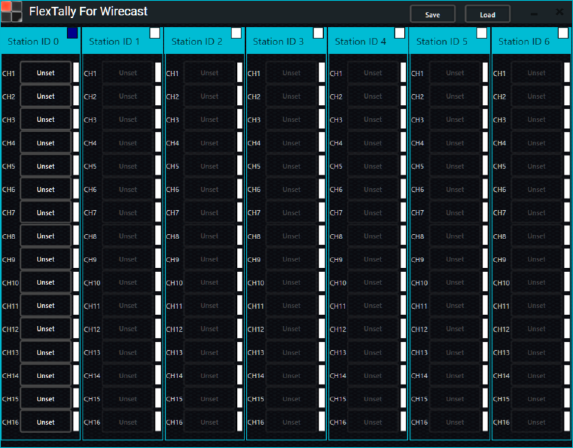
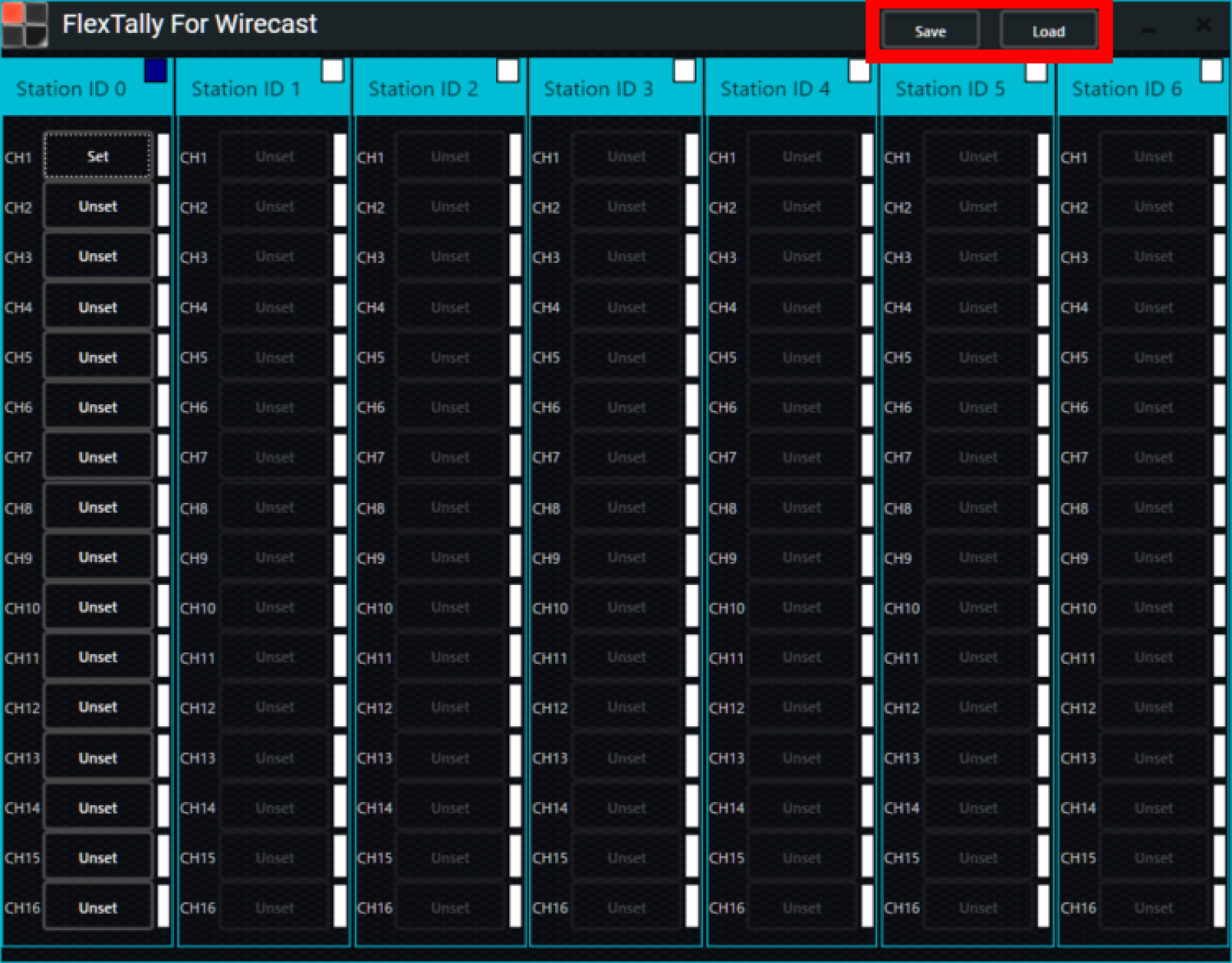
Lamp Unit settings with Wirecast
When connecting to the Wirecast switcher, additional settings using “FlexTally For Wirecast” are required.
Please complete the connection settings between the base unit and Wirecast before configuring the Lamp Unit settings
→ Connecting to Wirecast
The setup steps are as follows:
Start Wirecast.
Open “FlexTally For Wirecast”.
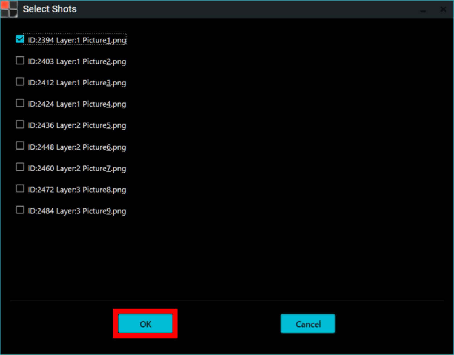
Select the Lamp Unit “Unset” you wish to do the setting.
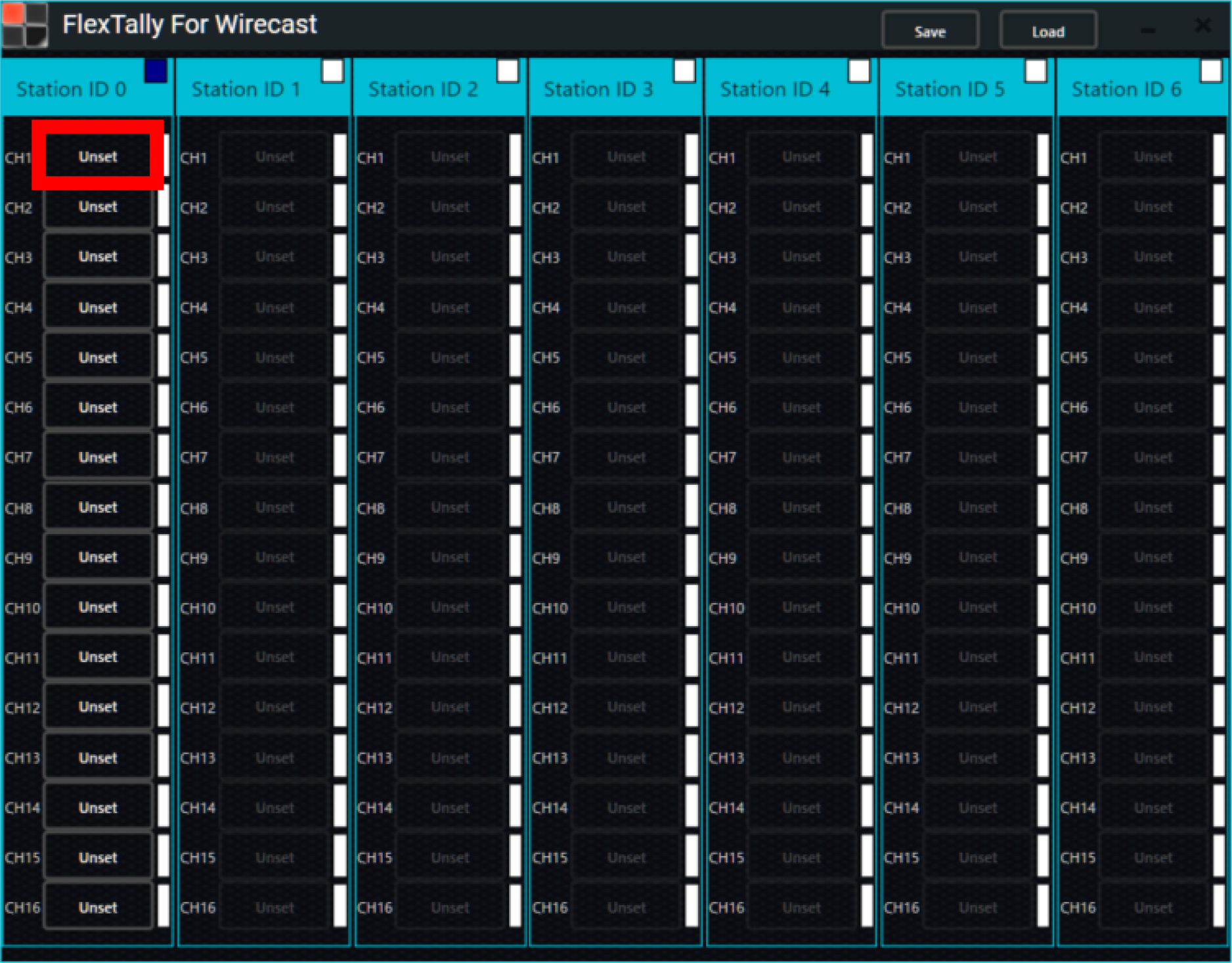
The “Select Shots” setting dialog box will appear. Select the shot you want to set for the Lamp Unit. Here, as an example, set “Layer:1 Picture1.png” for CH1 of Station ID 0.
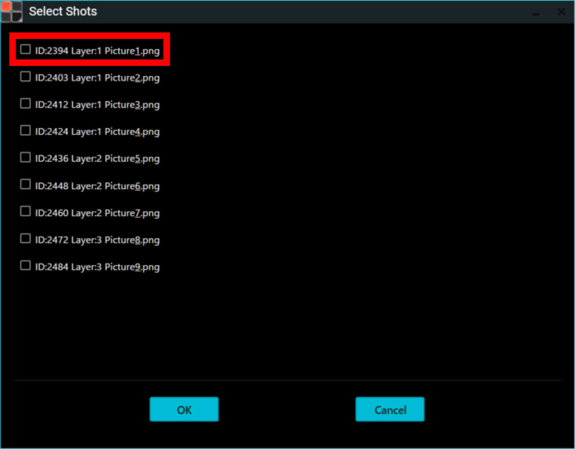
Click “OK”.
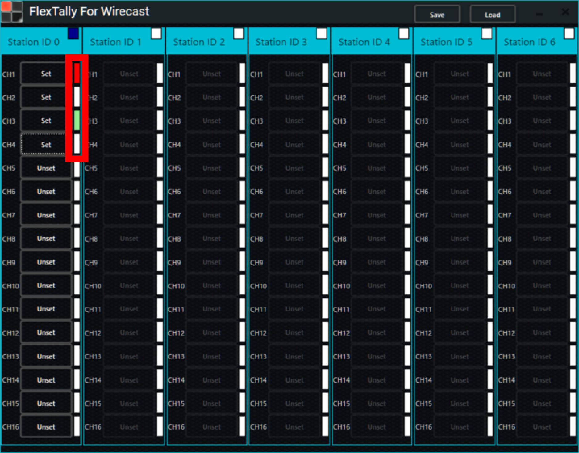
Once the setting is complete, the display will change from “Unset” to “Set.” Repeat the same procedure for other Lamp Units.

Click “Save” to save the settings. If you want to open a file that has already been configured, click “Load” and open the configuration file.
After completing the settings for all Lamp Units, perform transitions and preview selections in Wirecast and check the Lamp Unit’s on/off behavior. The corresponding lamp color notation on “FlexTally For Wirecast” will also light up red or green.
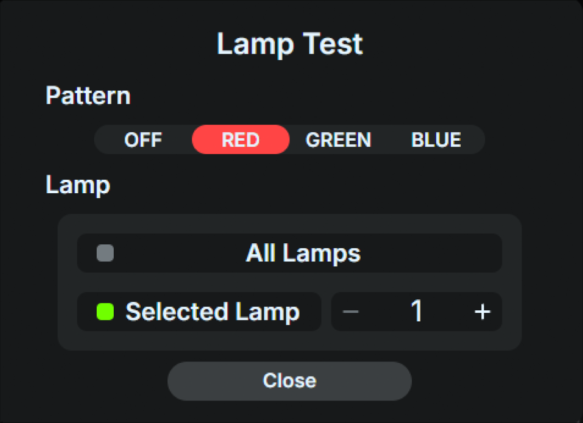
Lamp illumination test
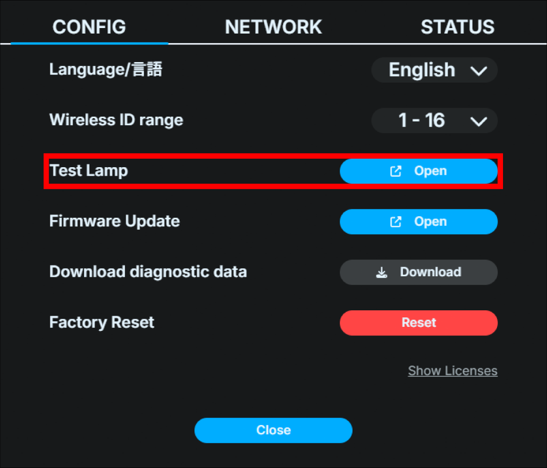
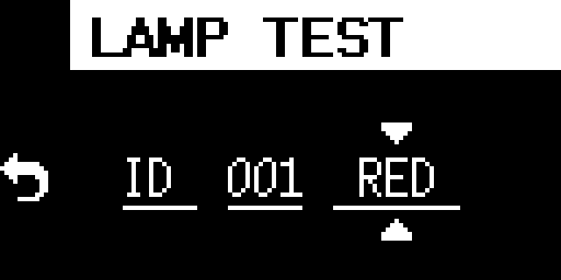
You can use the light illumination test to see whether the set Lamp Unit is connected properly.
Operation in the Web application
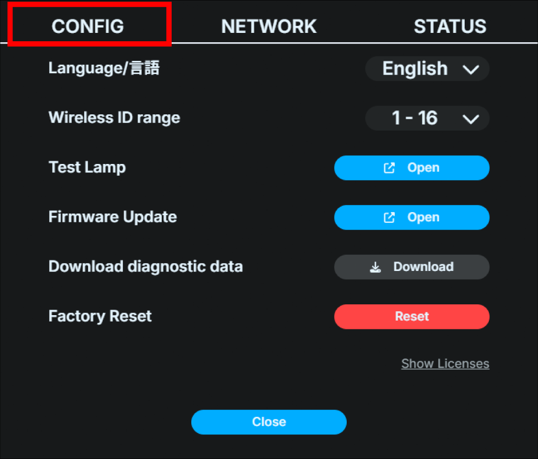
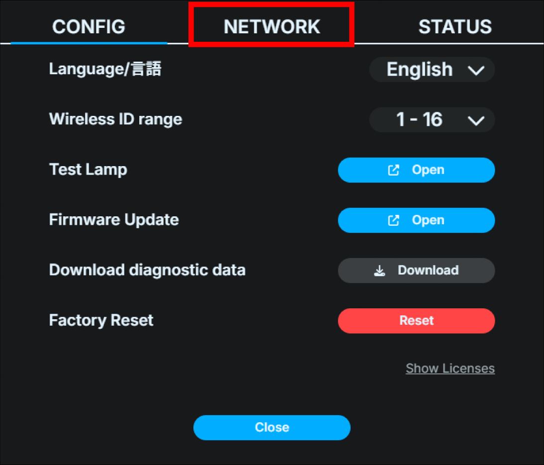
Press the gear button in the top right of the home screen.
Select the “CONFIG” tab in the dialog box that appears.
Click “Open” at Lump Test.
Select the pattern “RED / GREEN / BLUE” and select the checkboxes for all lamps or the target lamp ID to turn on the lights (the changes will be reflected immediately after selection). Select “OFF” to turn off the lights.
Operation on the Base Unit UI
Press the Confirm button on the main status screen to open the main menu, and select “Lamp Test”.

If you want to test a specific lamp ID, select the lamp ID.
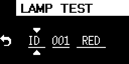
To test all Lamp Units, select ALL using the front operation buttons.

When you select RED / GREEN / BLUE using the front operation buttons, the lamp of the corresponding lamp ID will light up in the corresponding color. Select “OFF” to turn it off.
Checking wireless reception condition
Caution
The wireless reception strength display mode is available only on firmware version v1.1.5 or earlier. It is not supported on firmware v1.1.6 or later.
If the Lamp Unit power is turned on without an Ethernet connection, it will operate as a wireless master device. In this case, from the time the power is turned on until the Lamp Unit’s power button is pushed, it will operate in a mode that displays the wireless reception condition from the wireless access point to the wireless client device (hereafter referred to as “wireless reception strength display mode”).
When the Lamp Unit’s power button is pushed, it will resume normal operation as a tally light. Once it has entered normal operation, it cannot be switched back into wireless reception strength display mode.To return to wireless reception strength display mode, turn the Lamp Unit’s power off and then on again.
Information about wireless reception level display
In the wireless reception strength level display mode, the signal strength received from the wireless access point (master) is displayed on the secondary tally light (front) as a number from 1 to 5.
”5” is the strongest reception, and “1” is the weakest. When no signal is being received, an “X” and antenna mark are displayed on the tally light.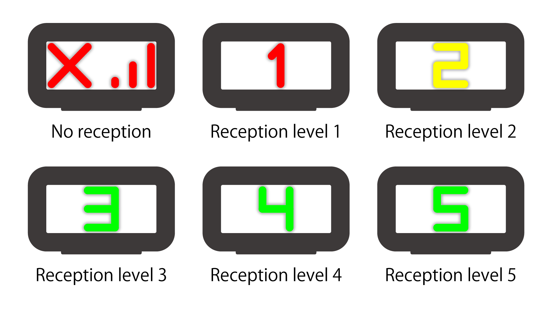
Tip
Communication between the Lamp Unit’s wireless master and the secondary units only occurs when a command is sent from the Base Unit.Therefore, when checking reception strength, please do it while performing Lamp illumination test or operating the switcher.
Tip
For stable wireless communication, we recommend installing the Lamp Unit’s wireless master so that it can receive signals at a reception level of “2”, preferably “3” or higher. For the installation environment, please also refer to the troubleshooting section below. → The Lamp Unit’s wireless connection is lost.
6 Basic settings and operation of the Base Unit
How to read the main status screen
Once the Base Unit is started, the main status screen will be displayed on the unit OLED display, showing the device’s status.
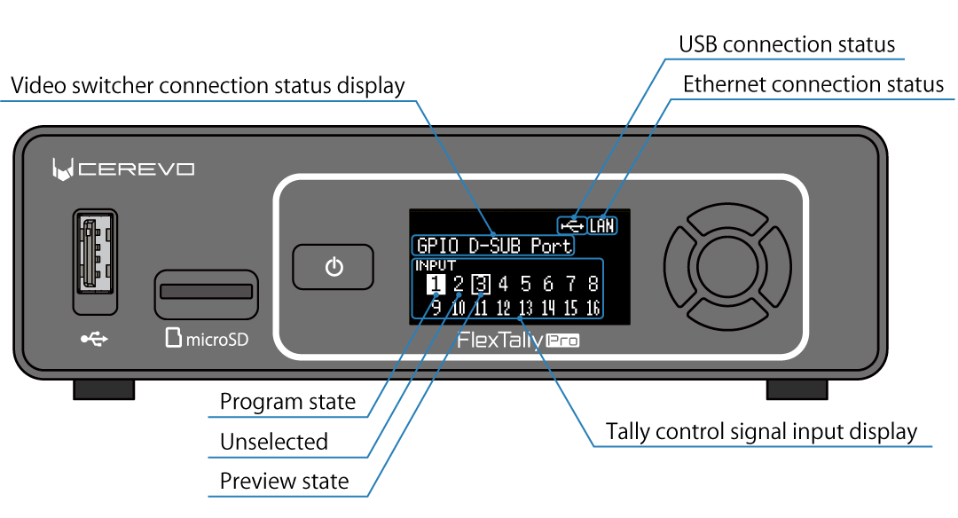
The information shown on the OLED is as follows:
USB/Ethernet connection status pictograms
The top row displays pictograms that indicate the connection status of the USB and Ethernet. When the USB is connected, the USB pictogram is displayed, and when the Ethernet is connected, the word LAN is displayed.
Video switcher connection status display
The next line displays the video switcher connection status. For GPIO connection, the words “GPIO D-SUB Port” are displayed. For Ethernet connection, the connection protocol and IP address with the video switcher are displayed. For USB connection, the connection protocol with the video switcher is displayed.
Tally control signal input display
The lower row displays the status of input numbers 1 to 16 of the tally control signals actually input to the Base Unit. If the input is in the program state, the corresponding number is shown in black in white background. If the input is in the preview state, the corresponding number is surrounded. Due to screen limitations, it is not possible to display statuses other than input numbers 1 to 16. If connecting to a video switcher using a method other than GPIO, you can use input numbers greater than 16, but in this case the input number will not be diplayed.
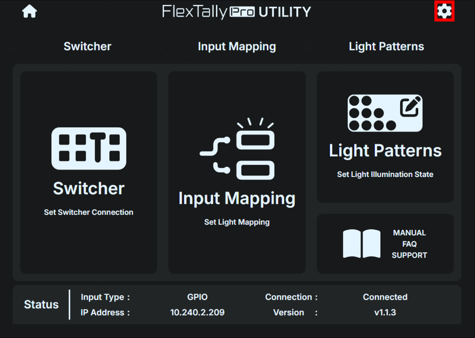
How to use FlexTally Pro Utility (a Web application)
The Base Unit has a built-in web user interface, FlexTally Pro Utility (web application).
How to access the web application
Use an Ethernet switch (sold separately) to connect the operation computer etc. to the same IPv4 subnet as the Base Unit.
Start any browser on the operation computer etc.
Boot the Base Unit, press the Confirm button on the main status screen to open the main menu, and select “Network”.
Select “Web login” in the Network menu.
表示されているURLを、ブラウザのURL欄に入力してください。
If the connection is successful, the FlexTally Pro web application will be displayed in the browser.
If you need to set the Base Unit’s IP address statically rather than via DHCP, first set the static IP address (fixed IP address) using the unit’s UI. -> How to set a static IP address (fixed IP address)
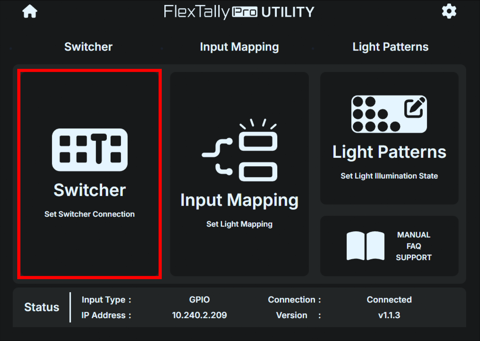
Below is the home screen of the web application.
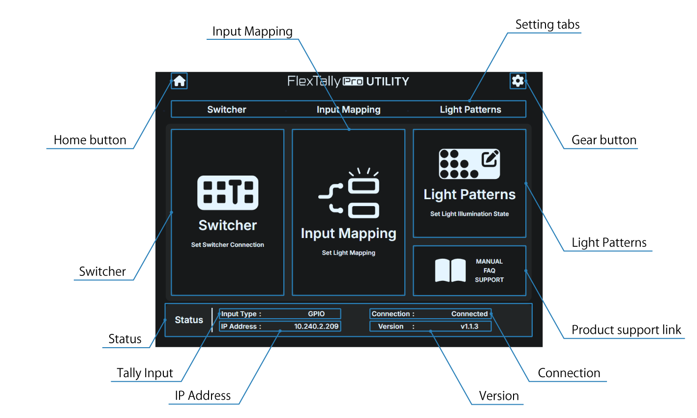
Home button
The home screen of the web application.
Gear button
For “CONFIG”, “NETWORK” and “STATUS” settings.
Setting tabs
For “Switcher”, “Input Mapping” and “Light Patterns” settings.
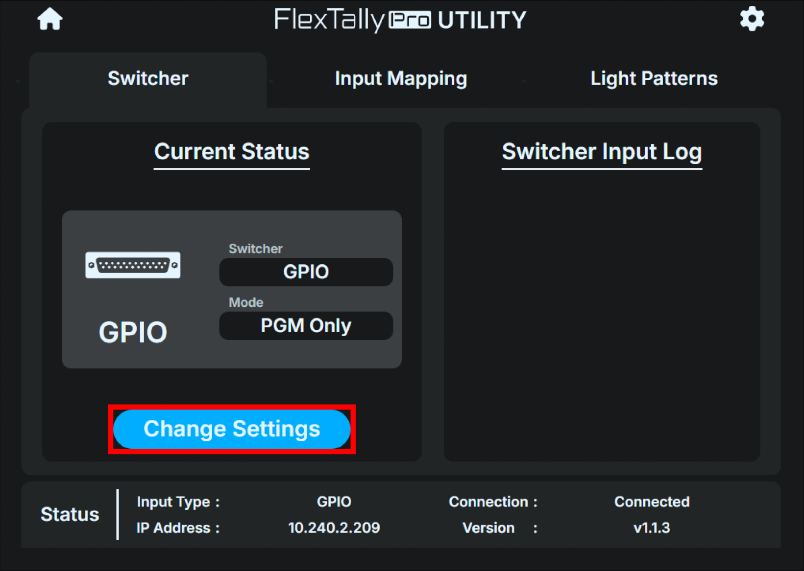
Switcher
Setting for connecting video switchers.
Input Mapping
Setting for Lamp Unit’s mapping.
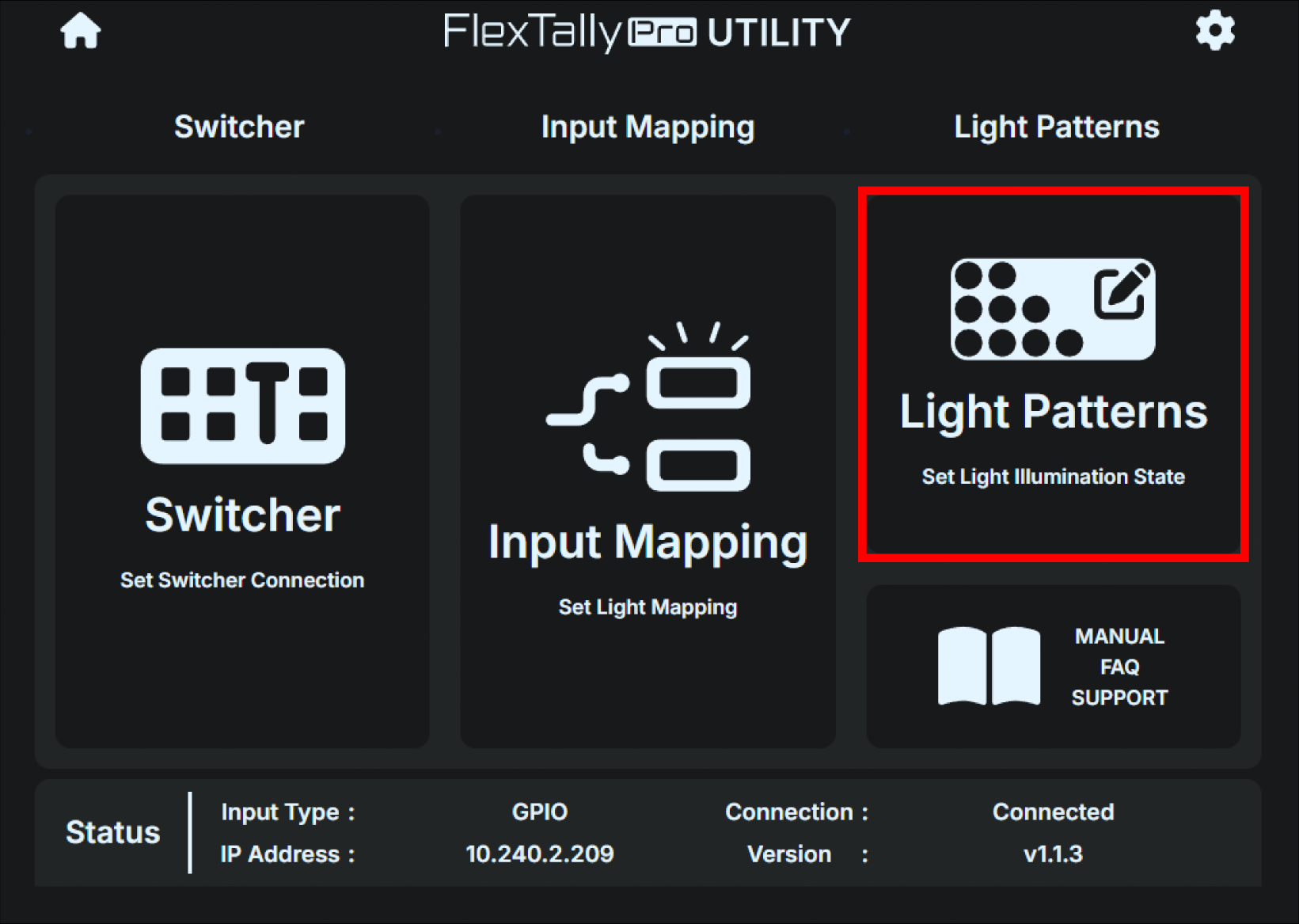
Light Patterns
Setting for the Lamp Unit light emission state.
Product support link
Product support pages
Status
The current status of each item is displayed. The following status are displayed.
Tally Input
Shows the type of connection interface between the currently configured video switcher and the Base Unit.
Connection
Shows the current connection status between the video switcher and the Base Unit.
IP Address
Shows the current Base Unit IP address.
Version
Shows the current Base Unit firmware version.
Base Unit network settings
The Base Unit’s Ethernet supports 100BASE-TX and can use IPv4 as the network protocol. Since the DHCP client is enabled by factory default, if you connect to a network with a DHCP server, the IP address will be obtained automatically.
If you need to manually set a static IP address (Fixed IP address), follow the steps below:
How to set a static IP address (fixed IP address)
Using the web application for the settings
Press the gear button in the top right of the home screen.
Click the “NETWORK” tab on the screen.
Click “OFF” on “DHCP”.
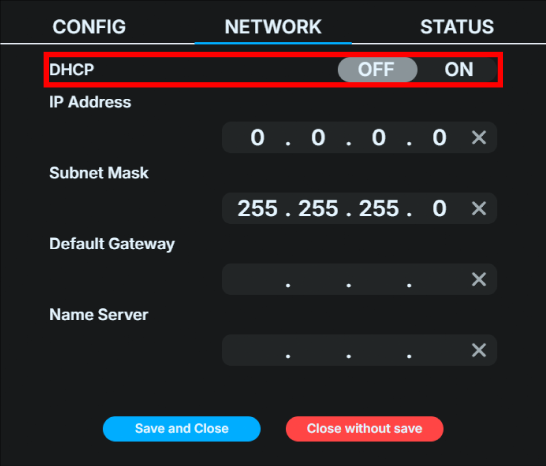
Set the IPv4 address, netmask, gateway, and name server.
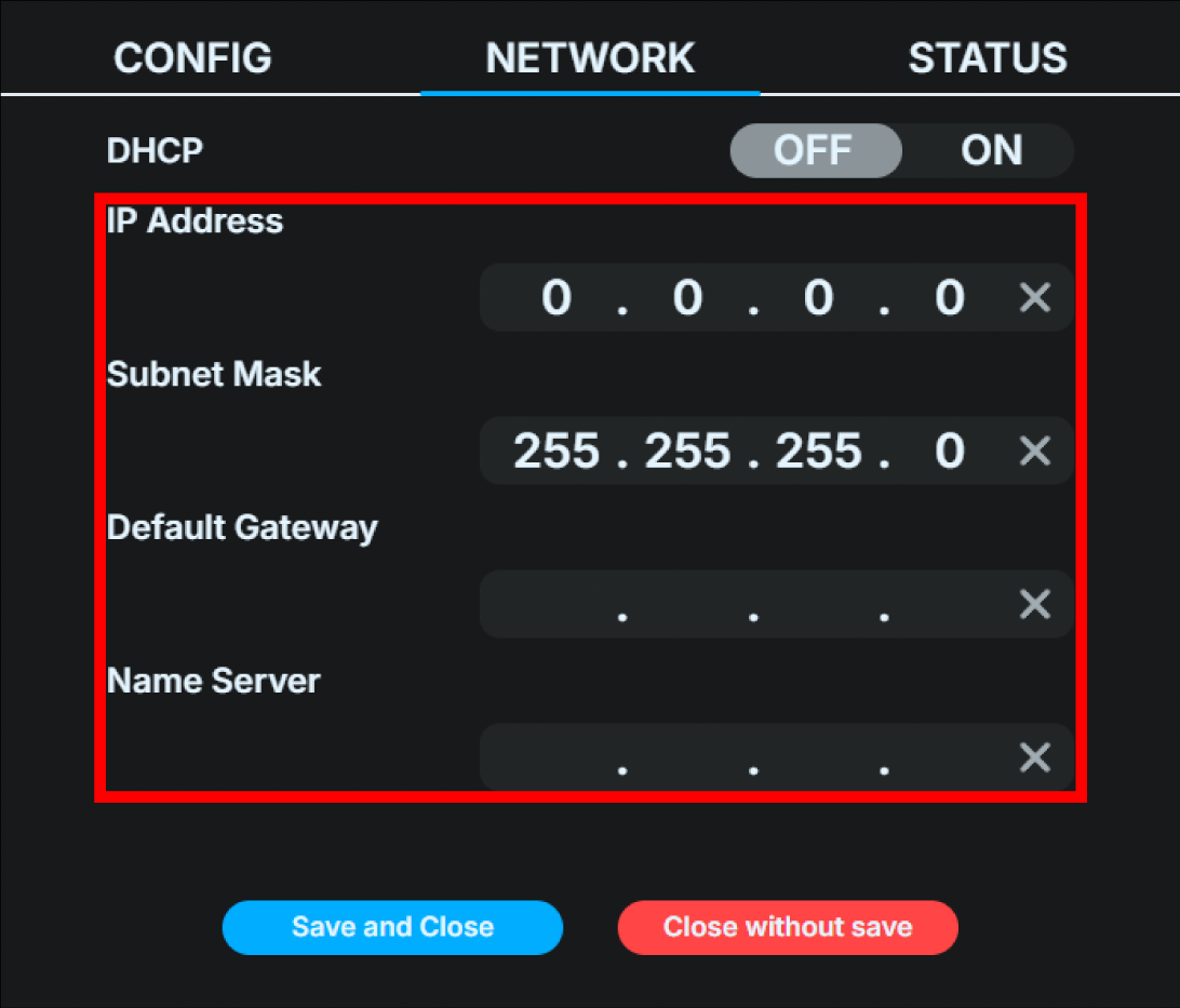
Click “Save and close”.
Using the Base Unit UI for the settings
On the main status screen, push the Confirm button on the main status screen to open the main menu, and select “Network”.
Select “DHCP” on the Network menu.
Select “OFF” on “DHCP” and push the confirm button.

Select “Static IP conf” added to the network menu. Push the confirm button.
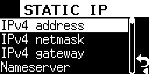
Enter the IPv4 address, netmask, gateway, and name server.
After entering each setting, select the check mark on the right to save the input and to complete the settings.
Changing the connection interface with the video switcher
GPIO is selected as the connection interface with the video switcher in the factory default setting. To change the default setting or change the current setting, follow the steps below.
Using the web application for the settings
Select “Switcher”.
Click the “Change Settings” button on the left side of the screen to display the settings dialog box.
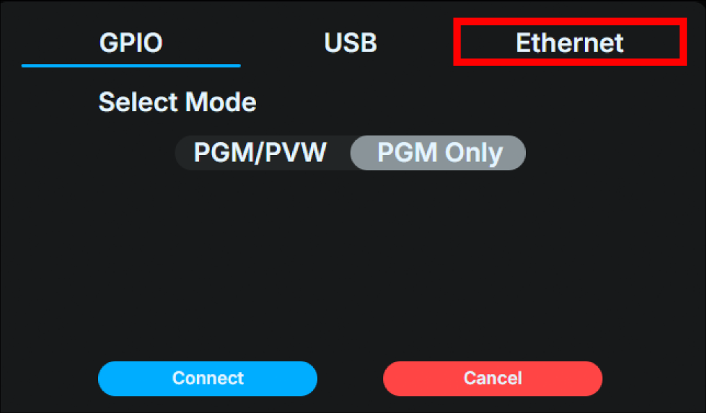
Click the interface you want to configure from the top of the dialog box and switch tabs.
Proceed with the settings for each interface you selected.
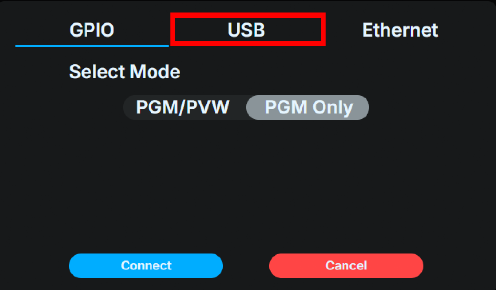
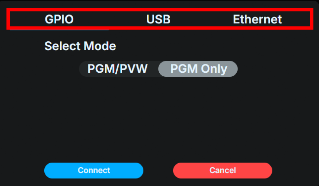
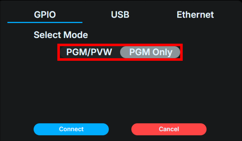
GPIO
Select mode
PGM / PVW or PGM Only
This setting determines whether PVW is enabled or disabled.
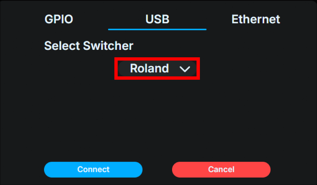
USB
Click the switcher
Select “Roland” from the “Select Switcher” pull-down menu.
Ethernet
Click the switcher
ATEM
TriCaster Type A
TriCaster Type B
vMix
Wirecast
Enter the switcher’s IP address.
Enter the switcher’s IP address.
Click the “Connect” button to connect to the switcher you have set up.
Even if you switch the enabled destination interface, the settings for the different interfaces (destination IP address settings, switcher model, etc.) will be saved.
Using the Base Unit UI for the settings
On the main status screen, push the Confirm button to open the main menu. Select “Switcher”.
Select “Interface” menu. Then, select “GPIO”, “Ethernet” or “USB”. Each is configured to use contacts (GPIO), Ethernet, or USB as the physical interface with the video switcher.

Depending on the physical interface you selected, set the following.
GPIO is selected
Select the GPIO menu and choose either “PGM” or “PGM/PVW”. “PGM” sets the input mode to 16 channels for the program state, and “PGM/PVW” sets the input mode to 8 channels for the program and preview states.

Ethernet is selected
Select Ethernet menu
Select “ATEM”,”TriCaster Type A”,”TriCaster Type B”,”vMIX”,”Wirecast” or “TSL UMD 5.0” depending on the video switcher you are connecting.
Next, enter the IPv4 address of the video switcher you wish to connect to.
USB is selected
The device is automatically set to “Roland.”
Once the setup is complete, proceed to the “Switcher” menu and attempt to connect to the switcher you have set up.
When it boots
For Ethernet and USB connections, when the Base Unit starts up, it automatically attempts to connect to the enabled interface. Even if the connection fails, it will continue to periodically try to connect to the enabled interface.
7 Lamp unit display and operation
Changing brightness
You can change the brightness by briefly pushing the power button. There are four levels of brightness: high, medium, and low. Each time you press it, it switches in the order of high → medium → low → super low.
Rear tally light status information
The rear tally light normally emits light according to the set lighting pattern. For information on how to set the lighting pattern, refer to Creating a lighting pattern. However, when the Lamp unit is in a specific state, it emits a special light to indicate that state. → Creating a Lighting Pattern
Lighting pattern |
Status |
|---|---|
Flashes red twice |
Preparing to connect to the Base Unit |
Flashing red |
Battery is low (when powered by battery) |
Flashing yellow |
Waiting for a response from the Base Unit (wired connection) |
Flashing green |
Not connected to LAN / Waiting for a response from the Base Unit (wireless connection) |
Flashing blue |
Connection successful (the light goes off 2 seconds after connection is successful) |
8 More convenient ways to use this product
This chapter explains more convenient ways to use this product. All of the following operations can be performed using the Base Unit web application, FlexTally Pro Utility.
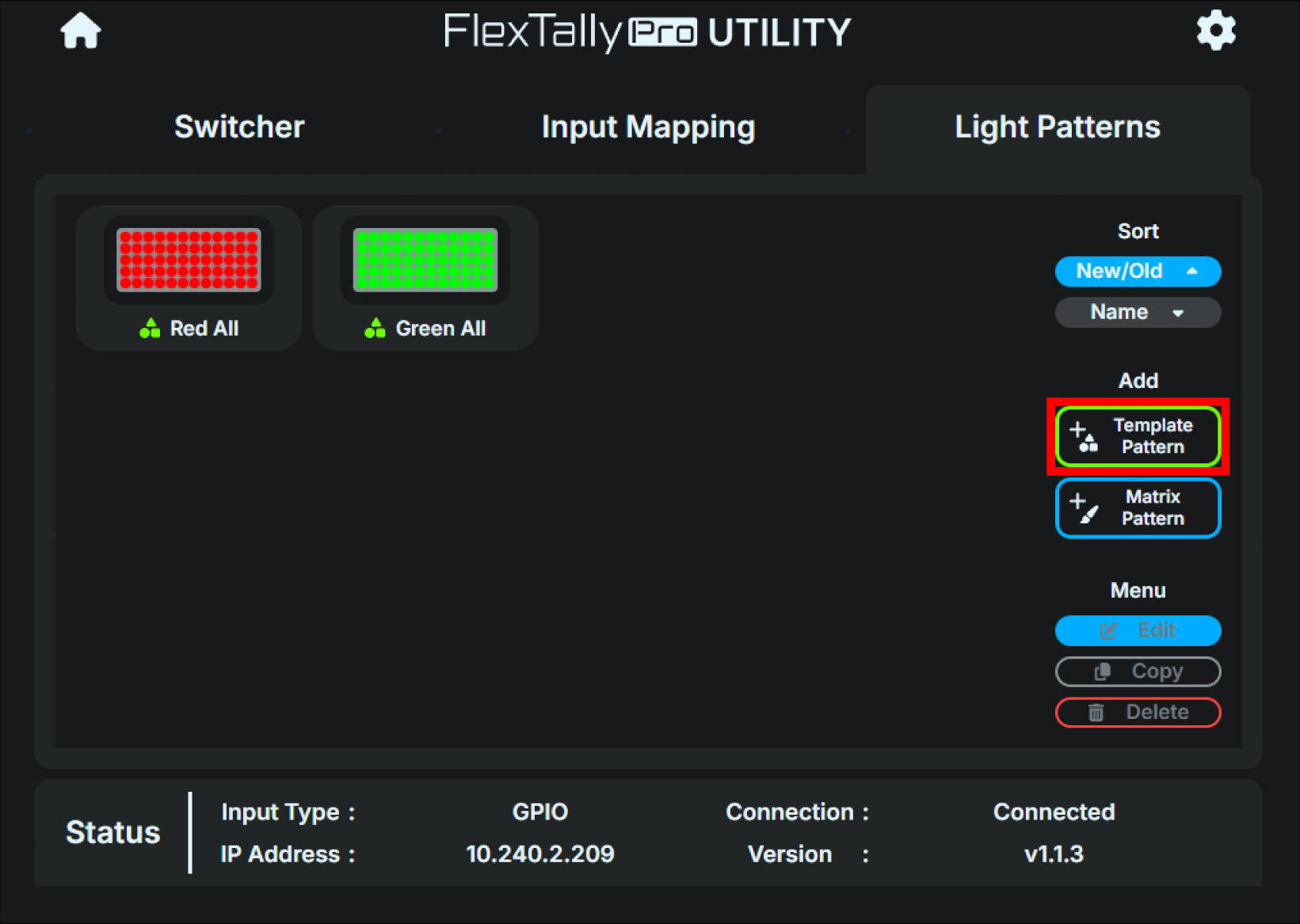
Creating a Lighting Pattern
This product allows you to edit the lighting color and pattern of the Lamp Unit as you wish. There are two ways to edit the lighting pattern: “template pattern” and “matrix pattern.” A template pattern specifies a predefined standard pattern and color, and is suitable for displaying simple figures or numbers. Note that Lamp Units that are set as a wireless client lamp can only display template patterns.
Editing with template patterns
The shapes that can be used in template patterns are as follows:
Full illumination
Numbers (up to two digits)
Circle
Triangle
Rectangle
Line
Outer frame
The editing steps are as follows:
On the Home screen, click “Light Patterns”.
Click the “Template Pattern” button in the additional menu on the right.
Select and create the shape and color in the dialog box that appears.
You can check the selected shape and color in “Preview.” Areas displayed in black are unlit areas.
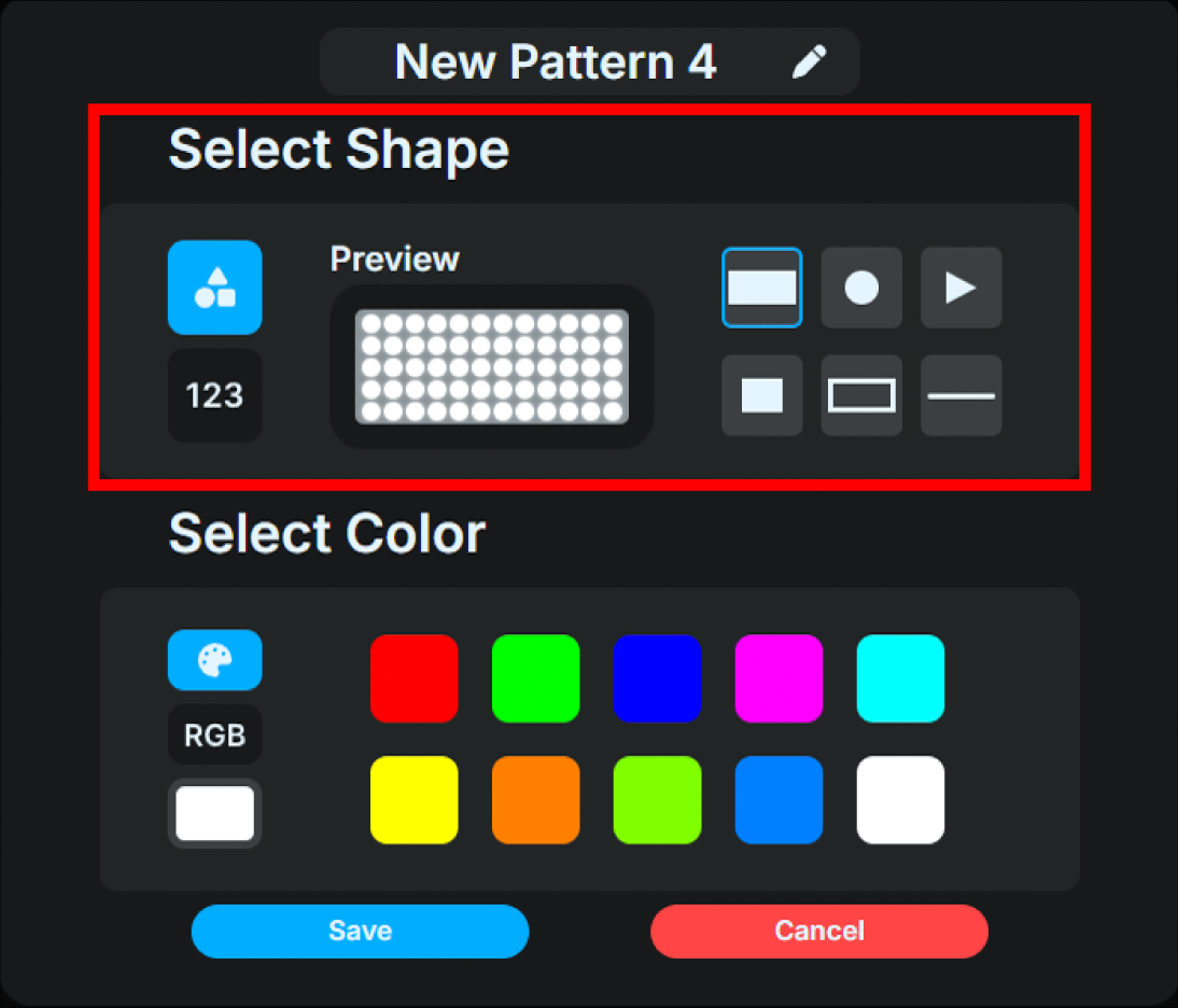
Colors can be set from a predefined palette or freely selected using RGB values.
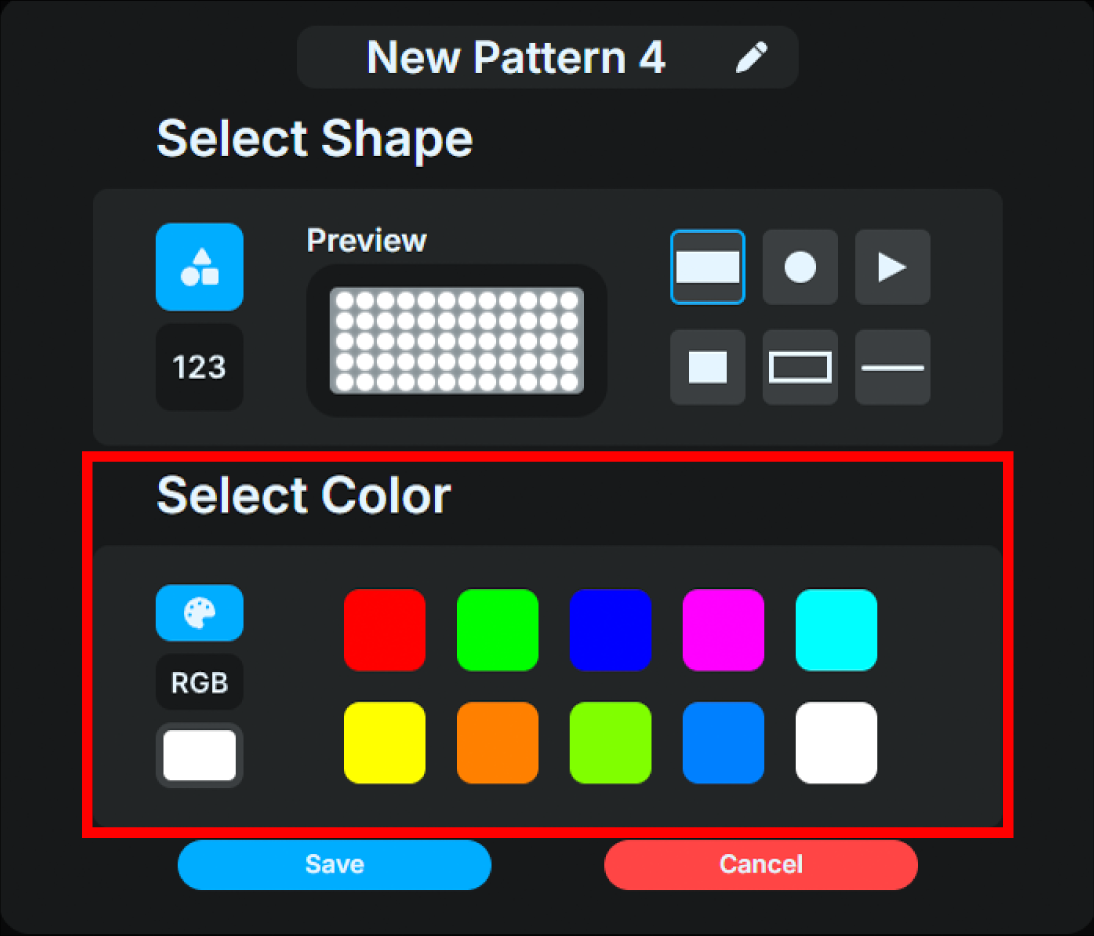
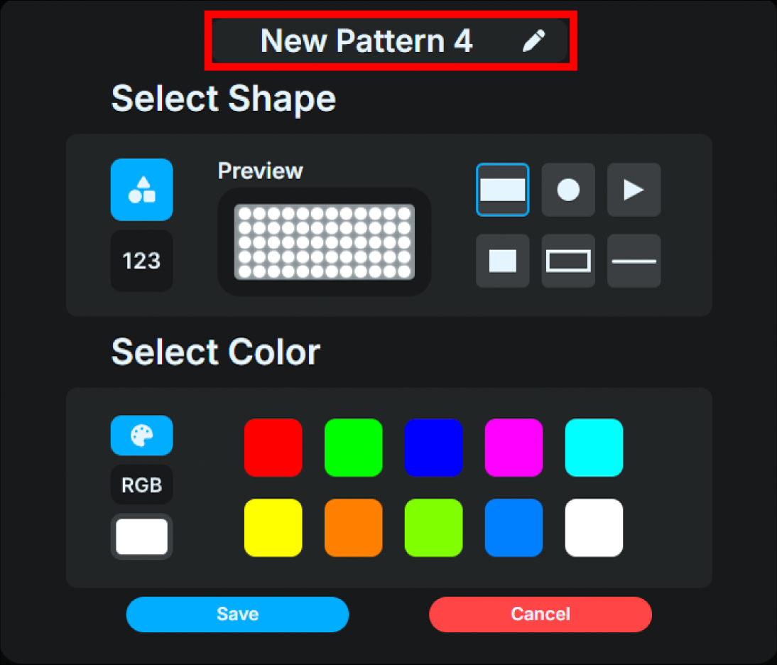
Name it as you like.
Click “Save” to save the setting.
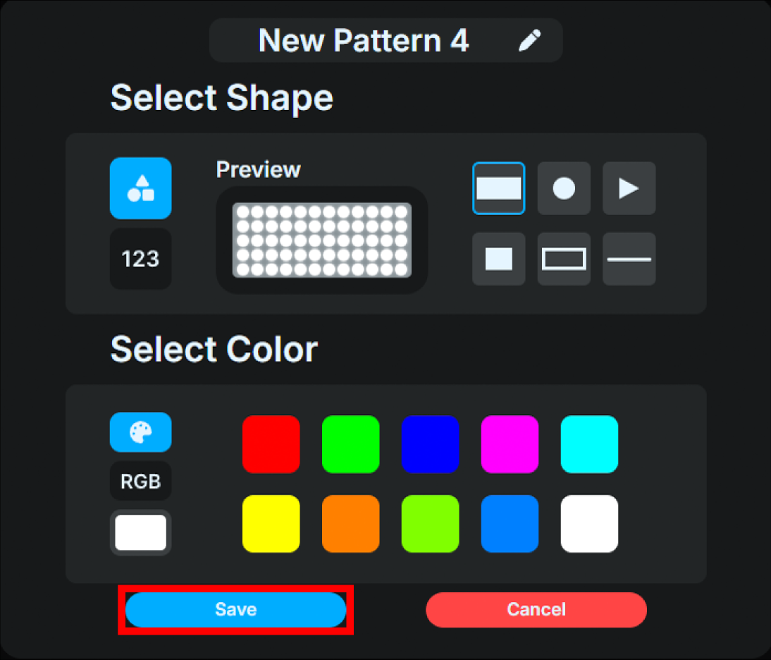
It will be added to the list of patterns you created.
Editing with matrix patterns
By editing the matrix pattern, you can create any bitmap of 12 dots horizontally and 5 dots vertically as the light emission pattern of the lamp.
The editing steps are as follows:
On the Home screen, click “Light Patterns”.
Click the “Matrix Pattern” button in the additional menu on the right.
Use each tool to select and create shapes and colors.
Areas displayed in black are unlit areas.
Colors can be set from a predefined palette or freely selected using RGB values.
Name it as you like.
Click “Save” to save.
It will be added to the list of patterns you created.
Below is the matrix creation screen description.
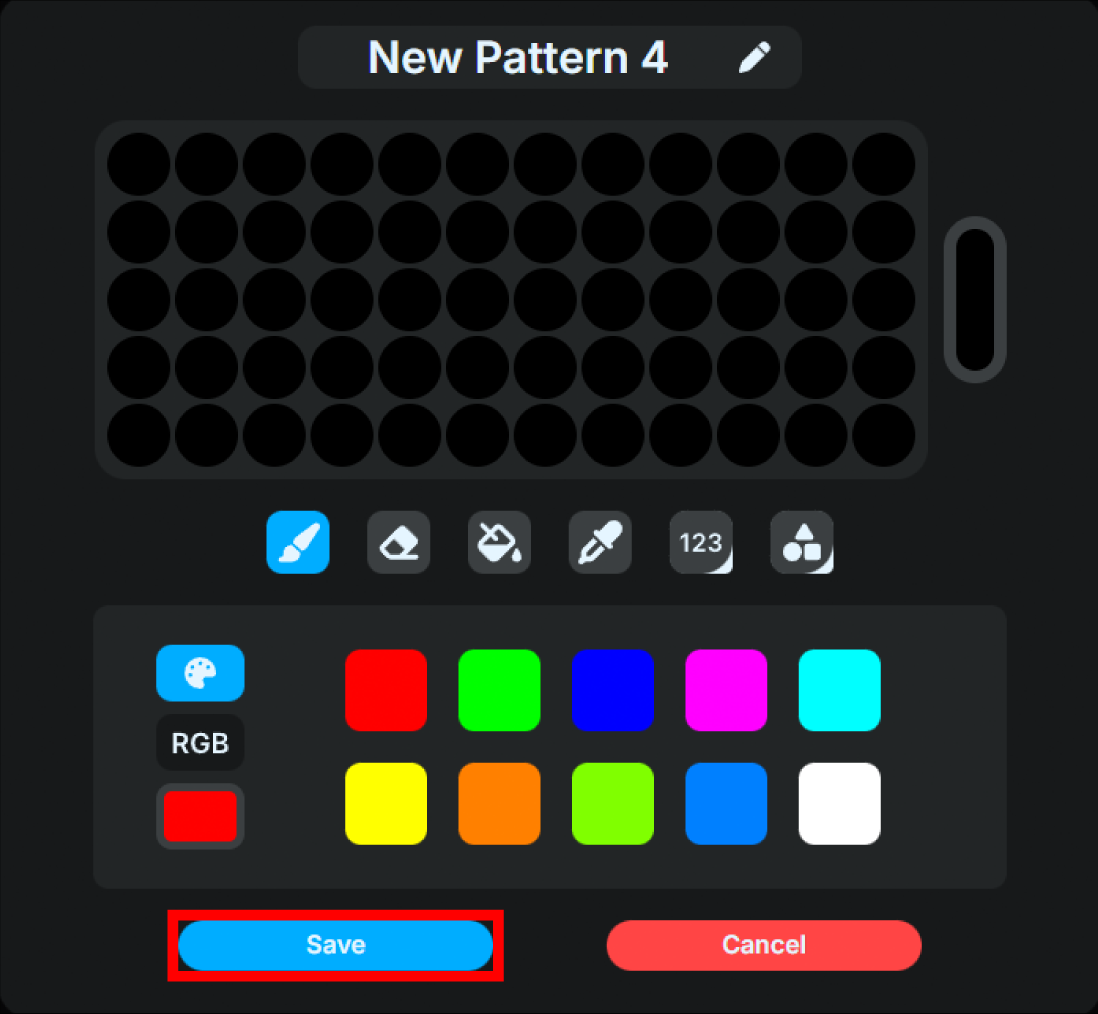
Click “Save” to save.
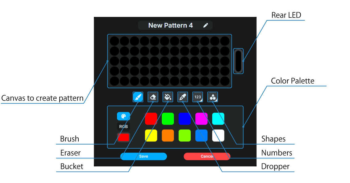
Canvas to create pattern
This is the area where the pattern will be drawn.
Rear LED
Settings for the rear LED.
Tool menu
Brush
Draw with the color you selected.
Eraser
Sets the dots selected by clicking and dragging to be unlit.
Bucket
Draw all dots with the selected color.
Dropper
Sets the color of the clicked dots to the current color.
Numbers
Place the selected number pattern in any position.
Shapes
Place the selected shape pattern in any position.
Color Palette
You can set the color to be drawn. The color can be chosen from a predefined palette or freely selected using RGB values.
Lamp Unit settings
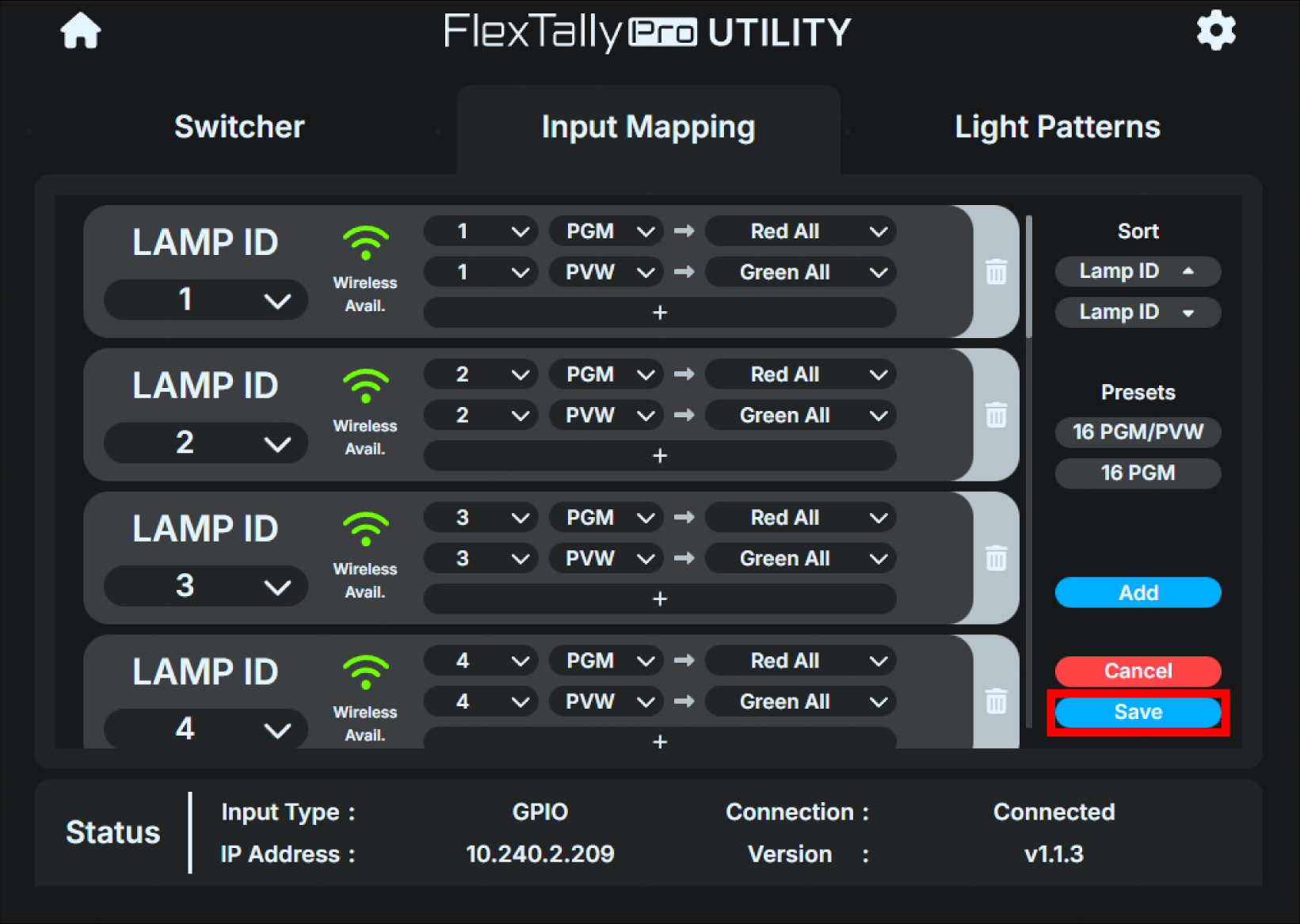
Lamp Unit settings allow you to link “input status and lighting pattern”. The ID for this setting is the “Lamp ID”. This setting determines which Lamp Unit will illuminate and how and when a given input reaches a specific status. You cannot create multiple settings for the same lamp ID. If you try to create one, an error will be displayed.
Below is the Lamp Unit settings control screen.
Click “Save” to save.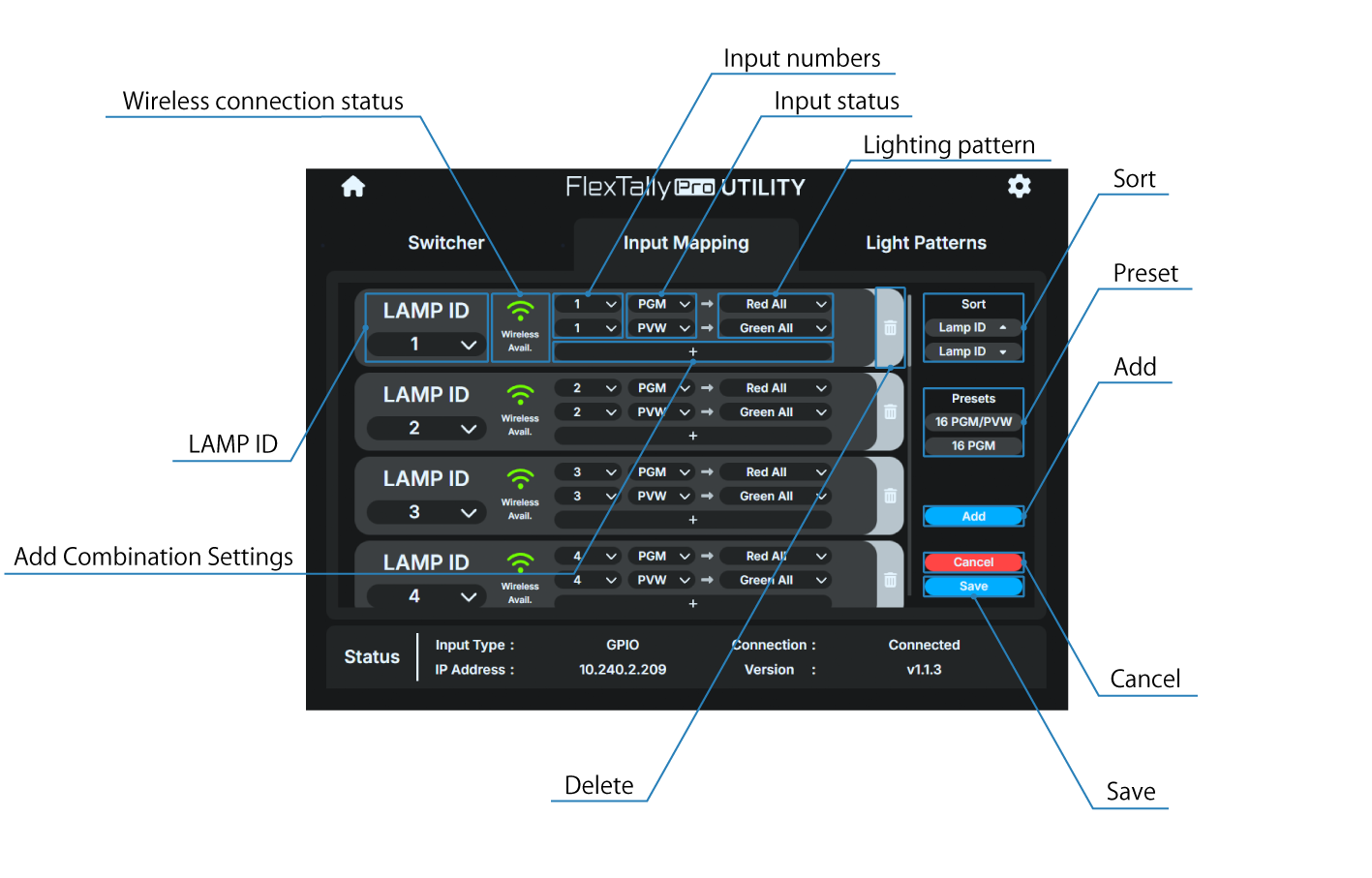
Lamp ID
You can select the lamp ID. The available IDs are as follows:
1 ~ 128
Wireless connection status
You can check whether or not a wireless connection is possible for the corresponding lamp. The displayed status is as follows:
Wireless connection possible
Wireless connection not possible
The range of lamp IDs that can be connected wirelessly has been exceeded. Please make a wired connection or change the range of lamp IDs.
→ Restrictions on lamp IDs of Lamp Units connected wirelessly
Input numbers
You can select the input number. The available numbers are as follows.
1 ~ 128
Input status
You can select the input status. The available statuses are as follows.
PGM
PVW
OFF
Lighting pattern
You can select the illuminating pattern. The available lighting patterns are as follows.
OFF
Red All
Green All
Any pattern created in “Light Patterns”
Add Combination Settings
You can add a combination setting of input number/status and lighting pattern.
Delete
You can delete the corresponding lamp setting.
Sort
You can sort lamp settings in ascending or descending order by lamp ID.
Preset
You can select a preset combination setting of input number/status and lighting pattern. The available presets are as follows.
16 PGM/PVW
For input numbers 1 to 16, each lamp lights up red in PGM status and lights up green in PVW status.
16 PGM
For input numbers 1 to 16, each lamp lights up red in PGM status and lights up green in PVW status.
Add
You can add lamp settings.
Cancel
Revert to the previously saved settings without the saving.
Save
Save the edited lamp settings.
How to edit Lamp Unit settings
Below is the Edit Lamp Unit Settings dialog box.

In the above settings image, the Lamp Unit with Lamp ID 1 will light up red when Input 1 is in PGM state, and will light up green when Input 1 is in PVW state.

In the above settings image, the Lamp Unit with Lamp ID 2 will light up red when Input 2 is in PGM state, and will light off when Input 2 is in PVW state.
The editing steps are as follows:
Go to the lamp setting dialog box.
From the pull down menu on “LAMP ID”, select the lamp ID you wish to set.

From the pull down menu on “Input number”, select the input number you wish to set.

From the pull down menu on “Input status”, select the status you wish to set.

From the pull-down menu on “Lighting pattern”, select the lighting pattern you want to set.

If you want to add a combination setting of input number/state and lighting pattern, click the “+” button in “Add combination setting” and follow the same procedure as above.

Click “Save” to save.
Screensaver
The Base Unit display is equipped with an OLED.
Because of the characteristics of OLED, display burn-in may occur if the same screen is displayed for a long period of time.
To prevent display burn-in, set the screensaver using the following procedure. Screensaver settings can only be made from the Base Unit UI. Settings cannot be made from the FlexTally Pro Utility.
The screensaver works only on the main status screen. It will not start when various settings menus are displayed.
On the main status screen, press the Confirm button to open the main menu and select “System”.

Select “Screensaver” and push the Confirm button.
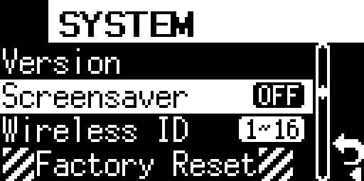
Select the desired time and push the Confirm button. After selecting, push the Confirm button again to return to the “System” menu.

The available times are:
Off
30 seconds
1 minutes
2 minutes
5 minutes
10 minutes
Firmware update
The firmware for the Base Unit and Lamp Unit can be updated. For detailed instructions, please refer to the firmware update guide.
How to check the current firmware version
Base Unit
You can check the Base Unit firmware version from the FlexTally Pro Utility or the Base Unit UI.
FlexTally Pro Utility
There are two different ways to check the firmware using FlexTally Pro Utility.
Method 1:
Use an Ethernet switch (sold separately) to connect the operation computer etc. to the same IPv4 subnet as the Base Unit.
Start any browser on the operation computer etc.
Boot the Base Unit, press the Confirm button on the main status screen to open the main menu, and select “Network”.
Select “Web login” in the Network menu.
表示されているURLを、ブラウザのURL欄に入力してください。
If the connection is successful, the FlexTally Pro web application will be displayed in the browser.
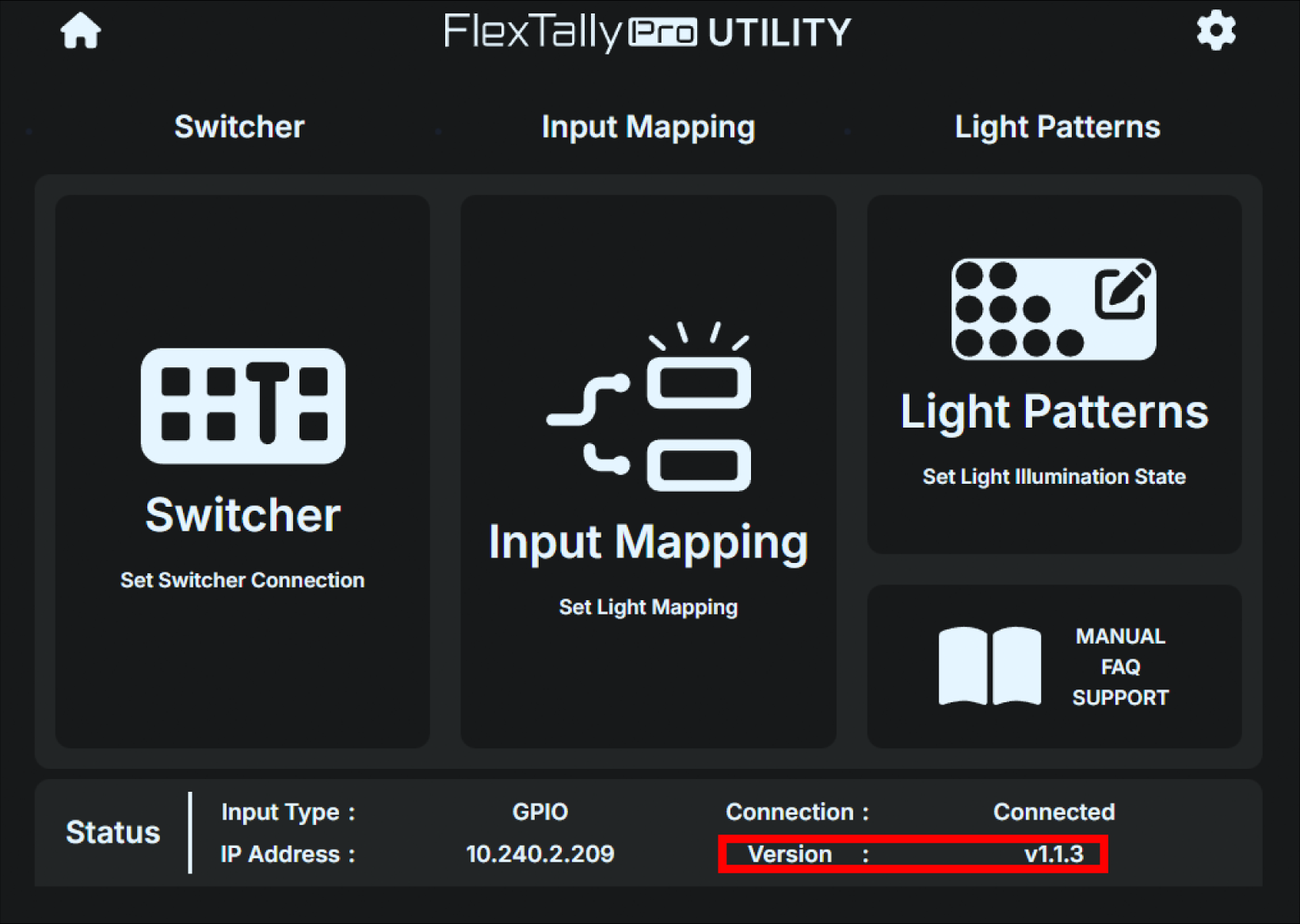
The current firmware version is shown in “Version” under “Status” at the bottom of the Home screen.
Method 2:
Use an Ethernet switch (sold separately) to connect the operation computer etc. to the same IPv4 subnet as the Base Unit.
Start any browser on the operation computer etc.
Boot the Base Unit, press the Confirm button on the main status screen to open the main menu, and select “Network”.
Select “Web login” in the Network menu.
表示されているURLを、ブラウザのURL欄に入力してください。
If the connection is successful, the FlexTally Pro web application will be displayed in the browser.
Press the gear button in the top right of the home screen.
Select the “STATUS” tab in the dialog box that appears.
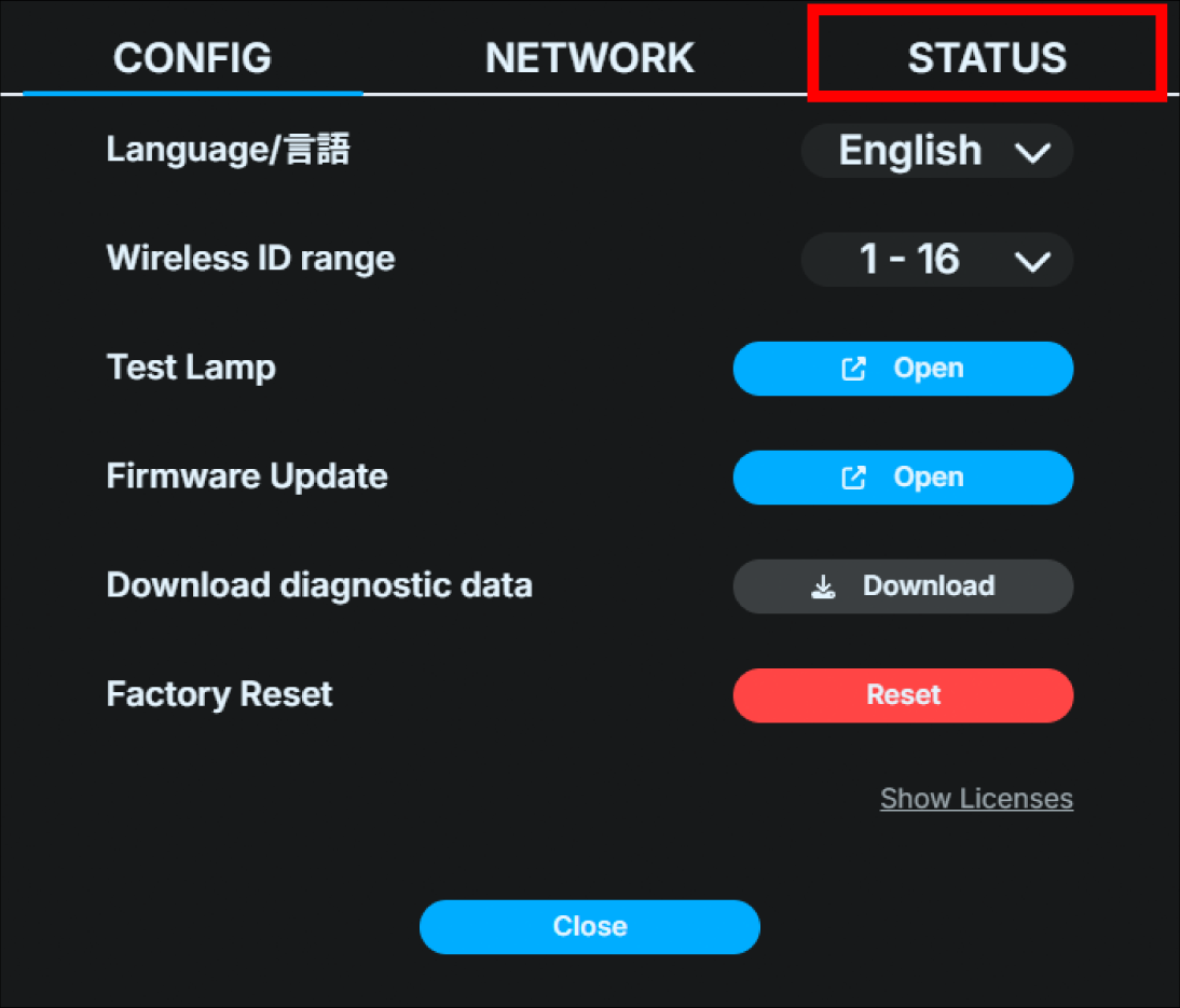
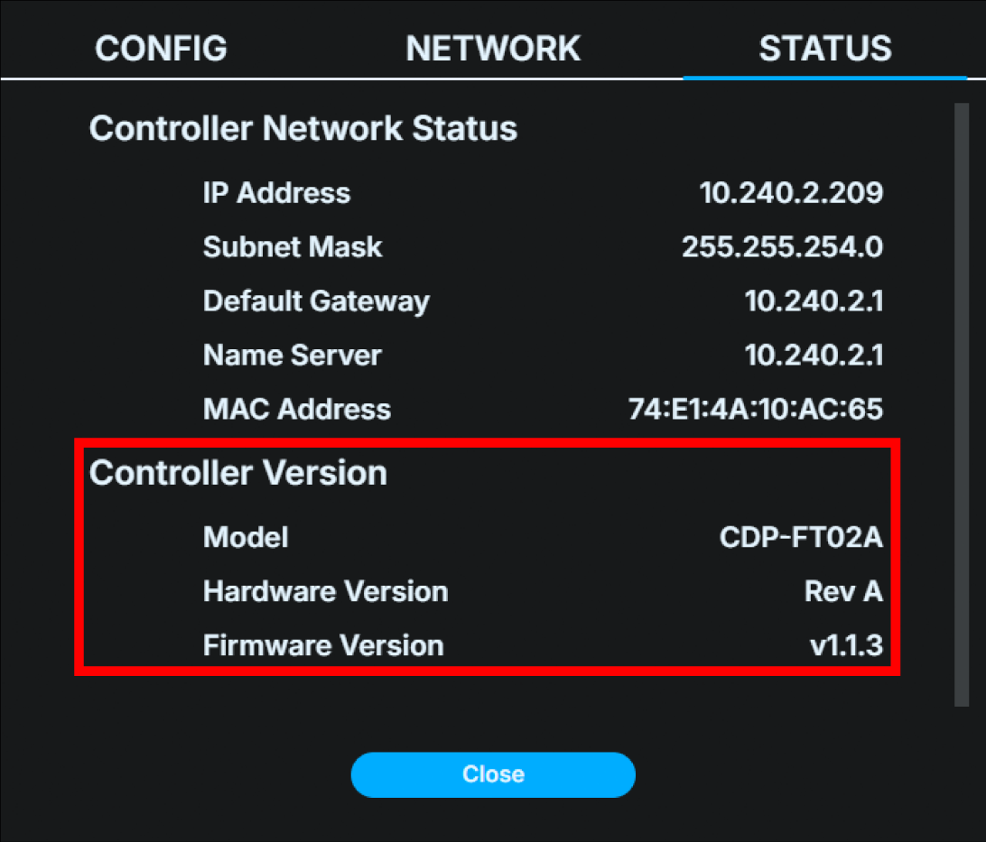
“Base Unit Version” shows the current firmware and hardware versions.
Base Unit UI
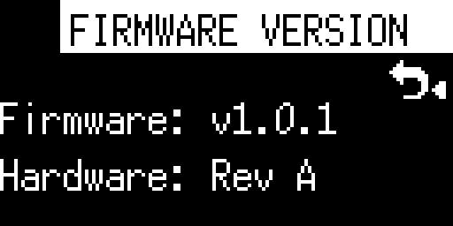
On the main status screen, press the Confirm button to open the main menu and select “System”.
Select “Version” and push OK button.

“Firmware Version” shows the current firmware and hardware versions.
Lamp Unit
The Lamp Unit firmware version can only be checked from the web application. It cannot be checked from the Base Unit UI.
Use an Ethernet switch (sold separately) to connect the operation computer etc. to the same IPv4 subnet as the Base Unit.
Start any browser on the operation computer etc.
Boot the Base Unit, press the Confirm button on the main status screen to open the main menu, and select “Network”.
Select “Web login” in the Network menu.
表示されているURLを、ブラウザのURL欄に入力してください。
If the connection is successful, the FlexTally Pro web application will be displayed in the browser.
Press the gear button in the top right of the home screen.
Click the “CONFIG” tab in the dialog box that appears.
Click “Firmware update”.
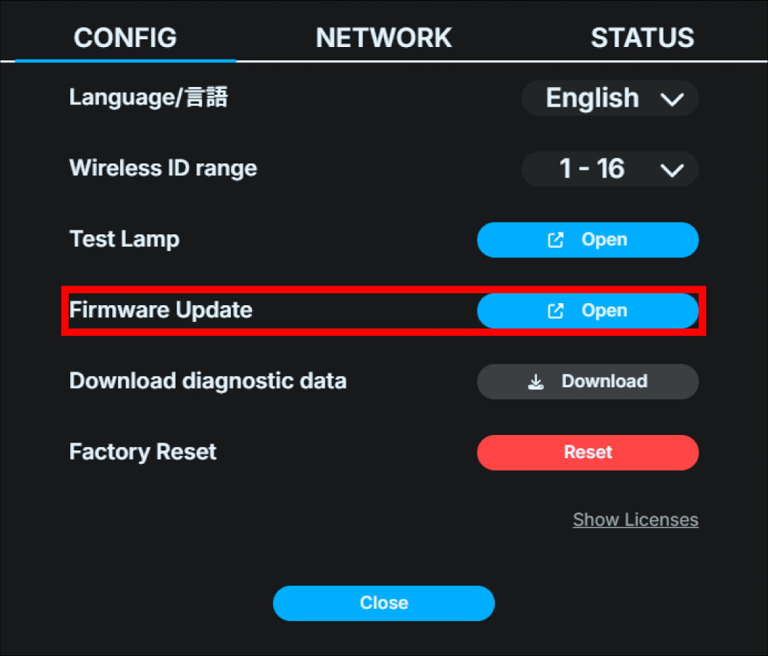
The lamp list shows the current firmware version for each Lamp Units.
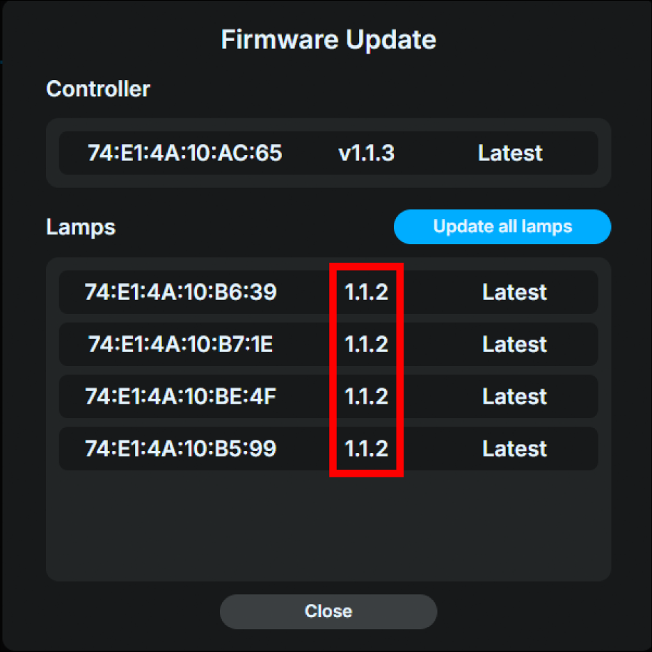
Factory reset
You can reset the Base Unit settings to the factory settings. *This operation cannot be undone. Please think carefully before proceeding.
FlexTally Pro Utility
Use an Ethernet switch (sold separately) to connect the operation computer etc. to the same IPv4 subnet as the Base Unit.
Start any browser on the operation computer etc.
Boot the Base Unit, press the Confirm button on the main status screen to open the main menu, and select “Network”.
Select “Web login” in the Network menu.
表示されているURLを、ブラウザのURL欄に入力してください。
If the connection is successful, the FlexTally Pro web application will be displayed in the browser.
Press the gear button in the top right of the home screen.
Click the “CONFIG” tab in the dialog box that appears.
Click the “Reset” button to the right of “Factory Reset” at the bottom.
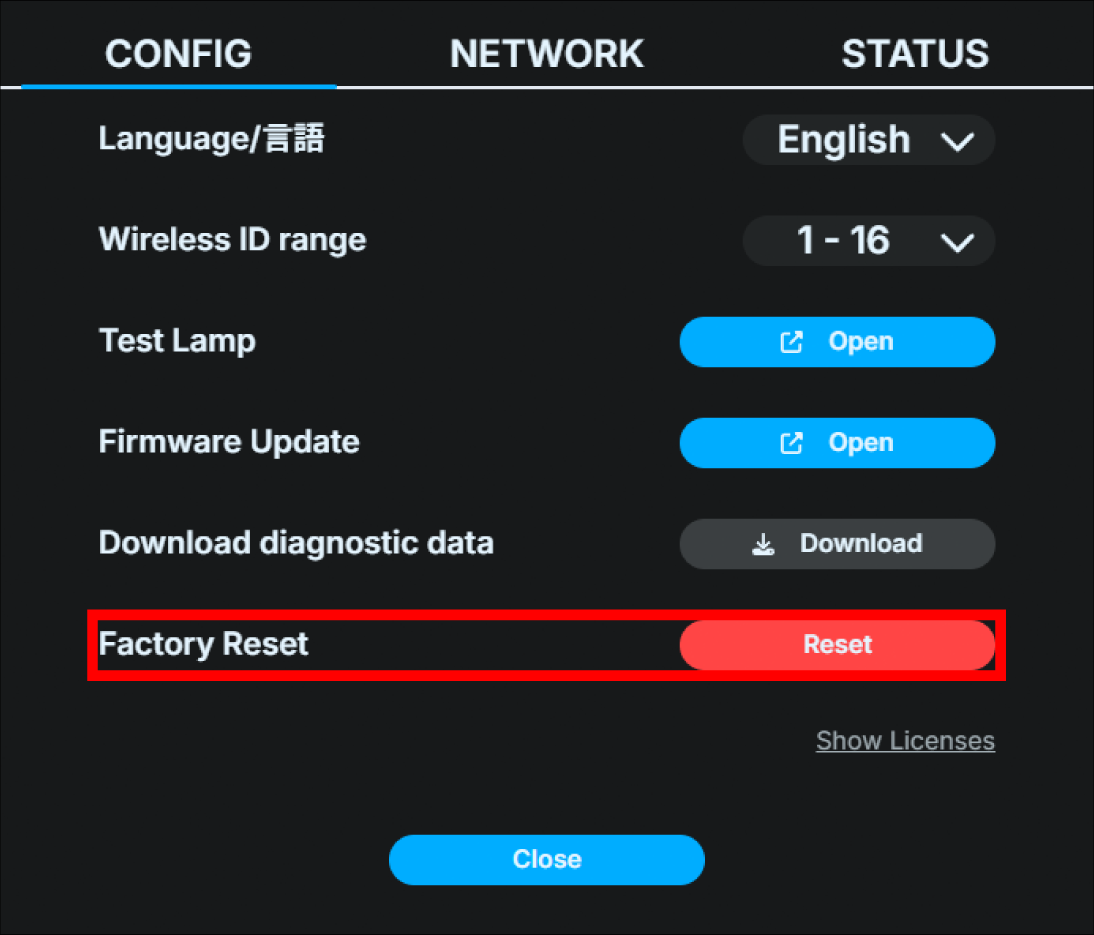
Click “OK” in the dialog box that opens. The reboot will begin.
As soon as the reboot begins, the FlexTally Pro Utility will be disconnected.
Once the reset is completed and the main status screen appears on the Base Unit’s OLED display, the factory reset is done.
Base Unit UI
On the main status screen, press the Confirm button to open the main menu and select “System”.
Select “Factory reset”.
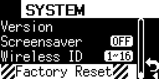
.Push and hold OK button. The reset will start.

Once the reset is completed and the main status screen appears on the Base Unit’s OLED display, the factory reset is done.
9 FAQ
Frequent Asked Question
Which switchers does FlexTally Pro support?
Please check the list of compatible switchers.
Note that models not on the list may also work. If you have any questions, please contact our customer support desk.
→ FlexTally Pro compatible switcher list
→ Contact our customer support
What kind of power supply should I use for the Base Unit and the Lamp Unit?
Please check Supplying power to the Base Unit and Powering the Lamp Unit.
What is the possible distance when connecting the Lamp Unit wirelessly?
Approximately 50m (164 ft) in an obstacle-free space.
The connection distance can be extended by using the relay wireless transmission function. For details, please check Wireless master Lamp Unit settings.
Can I use FlexTally Pro with a switcher that is not on the compatible switcher list?
It may be possible to use FlexTally Pro with a switcher that is not on the compatible switcher list. If you have any questions, please contact our customer support desk.
Can FlexTally Pro be connected and operated with devices other than video switchers?
If the device has a dry contact signal interface (GPIO output), it may be possible to connect and operate it even if it is not a video switcher. If you have any questions, please contact our customer support.
Can FlexTally Pro be used in combination with the previous FlexTally Station Unit, Lamp Unit, and GPIO cable?
The specifications are different from the previous FlexTally, so FlexTally Pro and the previous FlexTally cannot be used in combination.
Do you sell GPIO cables?
We sell various semi-customized GPIO cables at the Cerevo official store. We can also manufacture and sell GPIO cables for models not listed in the store. If you are interested, please contact our customer support desk.
Can Cerevo manufacture and sell GPIO cables for models that are not listed in the cable sales list?
We can also manufacture and sell GPIO cables for models that are not listed in the store. If you are interested, please contact our customer support desk.
Troubleshooting
I can not connect the Base Unit and my switcher.
Connecting via GPIO cable
Please check and make sure that the video switcher connection interface is set to “GPIO”.
→ Changing the connection interface with the video switcher
Additionally, check and confirm that the GPIO cable used for connection complies with the specifications of the Base Unit and video switcher.
Also, if you are using a switcher that allows users to freely set the GPIO output signal information, please check the settings again.
Connecting via USB
Please check and make sure that the video switcher connection interface is set to “USB”.
→ Changing the connection interface with the video switcher
Try replacing the USB cable used for connection with another one (preferably a new one) and check again whether it is connected properly.
We also recommend checking whether the connected video switcher is a model that supports USB connection with this product. Even if the video switcher is equipped with a USB connector, it may not be compatible with USB connection with this product.
→ Compatible switcher list
Connecting via Ethernet
Depending on the network environment and devices are connected, problems may occur with the connection of each device. In such cases, you may be able to connect successfully by turning off DHCP in the network settings of the connected Base Unit and the switcher, and manually setting a static IP address (fixed IP address).
→ How to set a static IP address (fixed IP address)
Issues Regarding Connectivity with TriCaster
If the TriCaster does not connect to the Base Unit, please check that the TriCaster password has been unlocked.
→ Connecting to Vizrt (NewTek) TriCaster switcher
If the tally status reflects on the controller only once after connecting to the “TriCaster Type A” and then stops updating, please try the “TriCaster Type B”.
The Base Unit power does not turn on or the Base Unit power is turned off.
Please check and make sure that the connected power supply meets all of the requirements listed in Powering the Base Unit. → Supplying power to the Base Unit
Please note that the Base Unit does not support PoE power reception.
The Lamp Unit power does not turn on or the Lamp Unit power is turned off.
Please make sure that the connected power supply meets all of the requirements listed in Powering the Lamp Unit. → Powering the Lamp Unit
If you are using a battery to power the Lamp Unit, check the remaining battery charge.
The Lamp Unit’s wireless connection is lost.
The wireless connection may fail due to obstacles, the building structure, the usage environment, etc. In that case, install more wireless master Lamp Unit to expand the wireless connection range, or adjust the installation location (ex: height and direction) of the wireless master Lamp Unit.
In addition, if the wireless master Lamp Unit is installed while stored in a rack case, it may not function properly as a wireless master Lamp Unit.
Also, in environments where a wireless connection is not essential, please consider using a wired connection.
Something is wrong with the Base Unit front display.
If the Cerevo logo is moving, that means the screen saver is ON.
→ Screensaver
If you see something similar to an afterimage, the display may be burned in. Please contact our customer support.
→ Contact our costomer support
Screensaver does not start
The screensaver is only available on the main status screen. The screensaver will not start when any of the setting menus are displayed.
Compatible Switcher List
You can find the latest compatible switcher list on the product page.
→ Compatible Switcher List
10 Appendix
DIP Switch Lamp ID Setting Table